Cartridge heaters - with internal thermocouples – ASB Heating Elements Ltd. Cartridge Heaters User Manual
Page 5
Cartridge Heaters - with internal thermocouples
I 5
Diam
eter
Leng
th
Lead
Leng
th
Diam
eter
Lead
Leng
th
Diam
eter
Lead
Leng
th
Diam
eter
Lead
Leng
th
Leng
th
Leng
th
Leng
th
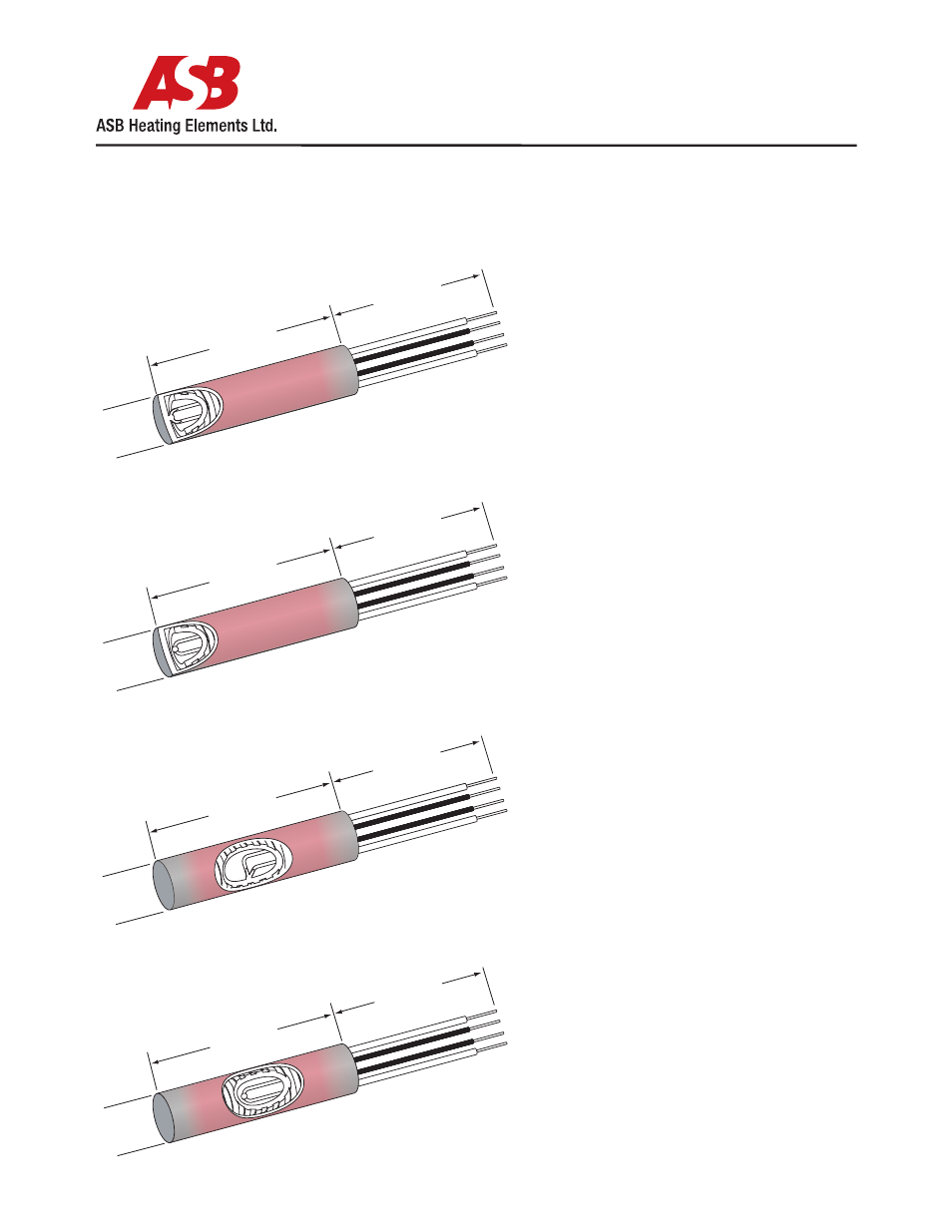
Internal Thermocouples
Internal thermocouples are built into the heater
assembly to monitor the internal or sheath
temperatures. These are useful as high limit devices
or in applications where space is at a premium. The
power and sensor leads exit the sheath together and
can be ordered with a variety of lead protections.
Not all thermocouple configurations are available
on smaller diameter heaters.
Type J and K calibrations are standard for the shown
constructions.
Grounded at Disc End, Figure 268
The thermocouple junction is grounded to the disc
end of the heater. This construction is commonly used
in hot runner applications. The disc end can be filled
with silver solder and ground flat. This will ensure
good contact when inserted into a flat end blind hole
Ungrounded at Disc End, Figure 269
The thermocouple junction is ungrounded and is
located just behind the disc end. This will give a
reference temperature of the part being heated.
Grounded at Centre, Figure 270
The thermocouple junction is grounded to the
sheath along the length of the heater. The standard
location is at the center of the heater, but can be
located anywhere along the lenght of the sheath.
This construction will provide a quick response
Ungrounded at Centre, Figure 271
The thermocouple junction is ungrounded and is
centered in the diameter of the sheath. The standard
location is at the center of the heater, but can be
located anywhere along the length of the sheath.
Typically used as a high limit in air or vaccum
applications
Figure 268
Figure 271
Figure 270
Figure 269