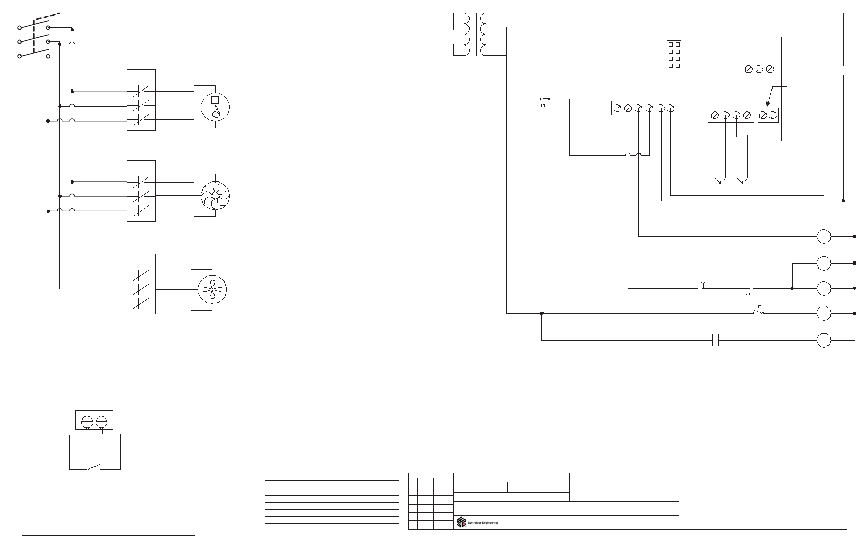
Fig. 1a – Schreiber Chillers 750AC MRI User Manual
Page 8
L3
L2
L1
1C
1W
1F
24V
Note: There are two fan
motors on this unit
2
4
V
A
C
G
ro
u
n
d
L
o
w
L
e
v
P
u
m
p
C
o
n
1
TC INPUTS
RETURN
DISCHARGE
+ - + -
N
C
C
O
M
N
O
ALARM
TIME
DELAY
4
2
1
0
Temp. Probes
Y
e
ll
o
w
Y
e
llo
w
B
la
c
k
R
e
d
Models:
Voltage:
Options:
Schreiber Engineering
12111 Park St. Cerritos, CA 90703
(562)-926-3855
(562)-926-0969 Fax
Phase:
Type: Air/Water Cooled Chiller
Notes:
All motors have internal overload protection unless otherwise shown
On all connections: L1 - Blue L2 - Black L3- Red
1001A/C
460/3
3
KETEMA1001460001
Ketema LP
2300 W. Marshall Drive
Grand Prairie, TX 75051
Electronic Controls
Automatic Tank Fill
REVISIONS
1
2
3
4
5
No
By
Date
LL-
W-
RS-
C-
FR-
Low Level Float Switch
Water Pump Contactor
Refrigerant Solenoid
Compressor Contactor
Fan Relay
LP-
Low Refrigerant Pressure Switch
HP-
High Refrigerant Pressure Switch
Red
1W
1F
1C
TFR
TFC
Water pump Coil
Fan Coil
Compressor #1 Coil
Tank Fill Relay
Tank Fill Solenoid Coil
LL1
Low Level Float
(Opens on Fall)
High pressure switch
(Opens on rise)
High pressure switch
(Opens on rise)
Low pressure switch
(opens on fall)
Tank fill float
(opens on rise)
Tank fill relay contact
Compressor
Water Pump
Fan Motor
See fig. 1A
Fig. 1A
The remote start stop is
located on the rear of the
control board this contact
is 24vac and must be
wired as shown when
switch is closed the unit
will run
Remote Start Stop