Electrical connections, Gps configuration, 2using the gps – MoTeC GPS-L10 User Manual
Page 4
2
Using the GPS
Electrical Connections
The GPS unit sends data to the logging device via an RS232 serial
connection.
The wiring between the GPS connector and the logging device should be as
short as possible, preferably less than 1 m (3 ft).
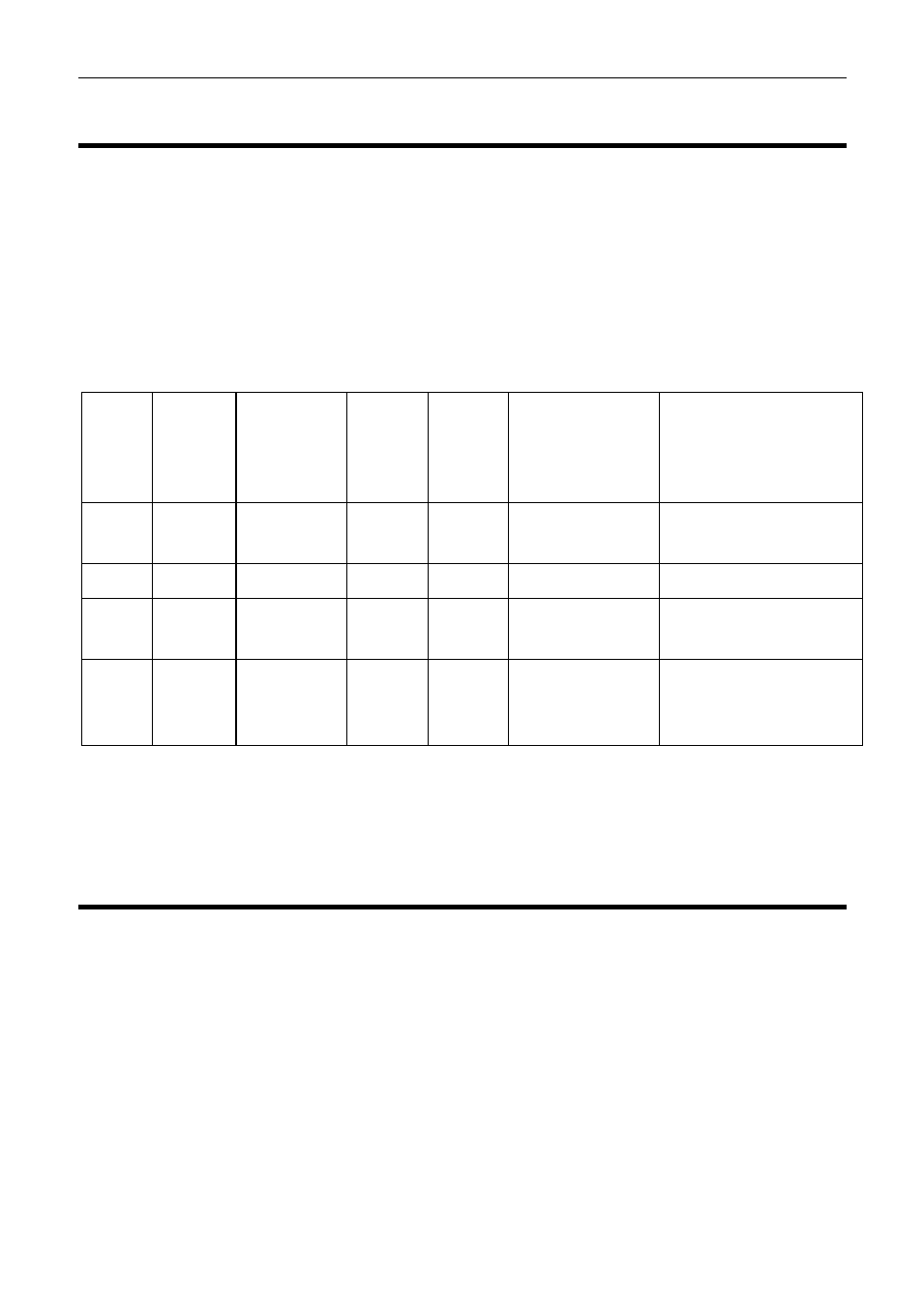
The following table shows how to wire the GPS unit to a number of MoTeC
logging devices.
GPS
Pin
GPS
Name
Logging
Device
Pin
Name
ADL3 SDL3
ACL
M84/M400/M600/
M800/M880 ECU
1
Bat -
Bat -
7
4
Bat- from
VIM/SVIM
15
2
TX
RX
79
34
15
18
3
RX
Not
Used
-
-
-
-
4
5V
5V
18
etc
14
Requires 5V
from
VIM/SVIM
9
Note that the ADL3 and SDL3 logging devices only have one serial
connection therefore if an ECU is to be connected then it must be connected
via CAN. (Note that not all ECUs have a CAN connection)
GPS Configuration
The GPS-L10 comes preconfigured from MoTeC to suit MoTeC data loggers.
The GPS-L5 comes preconfigured to suit MoTeC’s ‘Hundred Series’ and M84
ECUs.