Power supply alarm mute connector definition, Power supply alarm signal connector definition – Chenbro RM418 Series 6Gb/s 4-port 3.5 mini-SAS Backplane(80H10321516A1), For 8-bay 3.5 Hot-swap HDD Cage - Manual User Manual
Page 14
4-Port 6Gb/s Mini-SAS Backplane 80H10321516A1
User’s Manual
15Fl., No.150, Jian Yi Road, Chung Ho City, Taipei Hsien, Taiwan R.O.C.,
Tel: +886 2 82265500 Fax: +886 2 82265392 Email: [email protected]
14
w
w
w
.
c
h
e
n
b
r
o
.
c
o
m
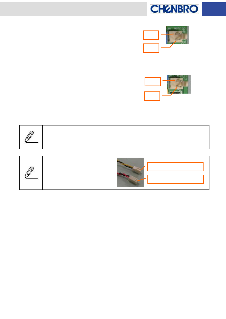
Power Supply Alarm Mute Connector Definition
Pin 1: Ground
Pin 2: Alarm mute signal output to PSU (Active low)
Power Supply Alarm Signal Connector Definition
Pin 1: Ground
Pin 2: PSU fail signal (TTL) input from PSU (Active low)
Only redundant PSU come with the failure alarm and alarm mute reset control via signal
connector. Make sure the redundant PSU that user applied come with the connectors
above.
This picture shows the standard
“2510 2-pin” type PSU alarm signal
connectors which fitting Chenbro
LED board.
Pin 1
Pin 2
Pin 1
Pin 2
Mute (Yellow & Black wire)
TTL (Red & Black wire)
- RM417 Series 6Gb/s 4-port 3.5 mini-SAS Backplane(80H10321516A1), For 8-bay 3.5 Hot-swap HDD Cage - Manual RM235 Series 6Gb/s 4-port 3.5 mini-SAS Backplane(80H10321516A1), For 8-bay 3.5 Hot-swap HDD Cage - Manual RM91250 6Gb/s 4-port 3.5 mini-SAS Backplane(80H10321516A1) Rev.A1 - Manual RM51424 6Gb/s 4-port 3.5 mini-SAS Backplane(80H10321516A1) Rev.A1 - Manual RM41416 6Gb/s 4-port 3.5 mini-SAS Backplane(80H10321516A1) Rev. A1 - Manual