Chenbro RM418 Series 6Gb/s 4-port 3.5 mini-SAS Backplane(80H10321516A1), For 8-bay 3.5 Hot-swap HDD Cage - Manual User Manual
Page 10
4-Port 6Gb/s Mini-SAS Backplane 80H10321516A1
User’s Manual
15Fl., No.150, Jian Yi Road, Chung Ho City, Taipei Hsien, Taiwan R.O.C.,
Tel: +886 2 82265500 Fax: +886 2 82265392 Email: [email protected]
10
w
w
w
.
c
h
e
n
b
r
o
.
c
o
m
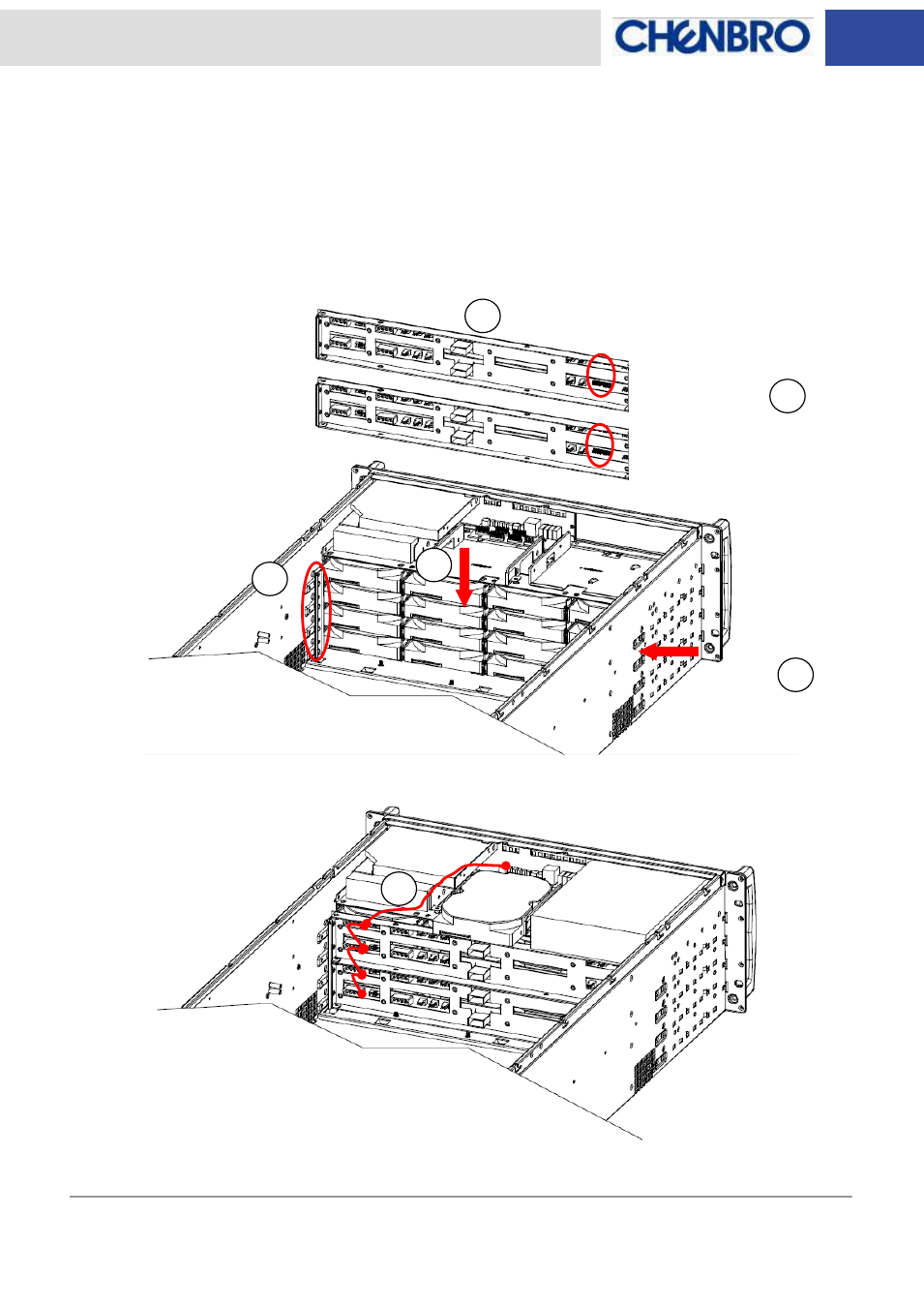
(B) Example of assembly procedure in RM41416B chassis
1. Get the complete 4U backplane assembly set (with two 2U backplane assembly sets) ready and
make sure the backplane guide rail is installed before backplane assembly.
2. Make sure the backplane ID is configured properly from bottom to top with starting from #1 to #4.
3. Slide the backplane assembly set into the chassis one by one.
4. Fix the backplane assembly set with screws on both sides of chassis.
5. Connect the LED board signal cable for each backplane and LED board.
6. Refer to “Backplane wiring” session for the cable connection.
Backplane ID#4
Backplane ID#3
Backplane ID#2
Backplane ID#1
Fix Screws
4
4
1
2
3
5
- RM417 Series 6Gb/s 4-port 3.5 mini-SAS Backplane(80H10321516A1), For 8-bay 3.5 Hot-swap HDD Cage - Manual RM235 Series 6Gb/s 4-port 3.5 mini-SAS Backplane(80H10321516A1), For 8-bay 3.5 Hot-swap HDD Cage - Manual RM91250 6Gb/s 4-port 3.5 mini-SAS Backplane(80H10321516A1) Rev.A1 - Manual RM51424 6Gb/s 4-port 3.5 mini-SAS Backplane(80H10321516A1) Rev.A1 - Manual RM41416 6Gb/s 4-port 3.5 mini-SAS Backplane(80H10321516A1) Rev. A1 - Manual