BatteryMINDer SCC015 User Manual
Page 3
Rev. B-062811
- 3 -
P/N VDC SCC005-015-MNL
BatteryMINDer
®
SCC005 & 015
wish to, without leaving holes behind. You may also choose to use the
screw holes provided.
Connect output wires from solar panel to solar controller by sliding terminal
cover on controller to expose terminals beneath. Be careful to observe
correct polarity. Do one wire at a time. Do not have solar panel exposed
to sunlight. Do not touch wires together.
Connect cord set (supplied) to battery clamps or directly to terminals
(depends on battery type) Observe polarity indications on ring end of
wires:
RED
= + (positive)
BLACK/
BLUE
= - (negative).
Solar Controller has three (3) separate LED status indicators: They are:
YELLOW
= Solar Power - Lit when sufficient sunlight is available to
charge/maintain/desulfate battery(s)
RED
= Polarity Reversed (Battery only) If lit
RED
, reverse battery
connector wires to battery.
GREEN
= Battery Charge If lit (solid) battery is being charged-
desulfated. If it blinks (flashes) battery is being maintained and
desulfated (if required).
IF NO LEDs ARE LIT, SOLAR OUTPUT IS NOT SUFFICIENT TO ALLOW
ANY FUNCTIONS TO OCCUR. YOU MUST WAIT FOR ADDITIONAL
SOLAR OUTPUT TO OCCUR, BEFORE ANY ACTION CAN TAKE
PLACE.
Note: Never try to use your SCC005/SCC015 solar controller with any
other solar panels in excess of 15 watts total. Doing so will burn our
your unit and void your 5-year Warranty and 1-year Guarantee.
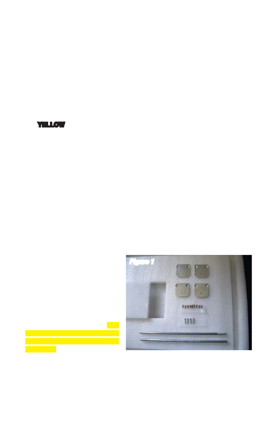
MOUNTING INSTRUCTIONS
Kit with Temporary and
Permanent Mounting Brackets.
See Figure 1.
The panel comes with two
arms for angling the panel for a
temporary installation and four
brackets for installing the panel
permanently on a surface. The
brackets and screws are in the
cut-out in the foam underneath
the panel.
Mount the panel with the black
side up and silver side down. It must be placed in a location where there
is maximum sunlight.
Try to locate an area where you do not have to extend the cord. If this is
not possible, the cord may be extended by an additional 5 feet.
•
•
•
Figure 1