BatteryMINDer 12151 User Manual
Page 5
Rev. A-072610
Page 5
P/N VDC 12151-MNL
BatteryMINDer
®
Model 12151
MOUNTING CHARGER FOR
CONTINUOUS USE
WARNING – Never alter AC line
cord or plug provided. If it will not
fit in the outlet, have the proper
outlet installed by a qualified
electrician. Improper connection
can result in the risk of electric
shock.
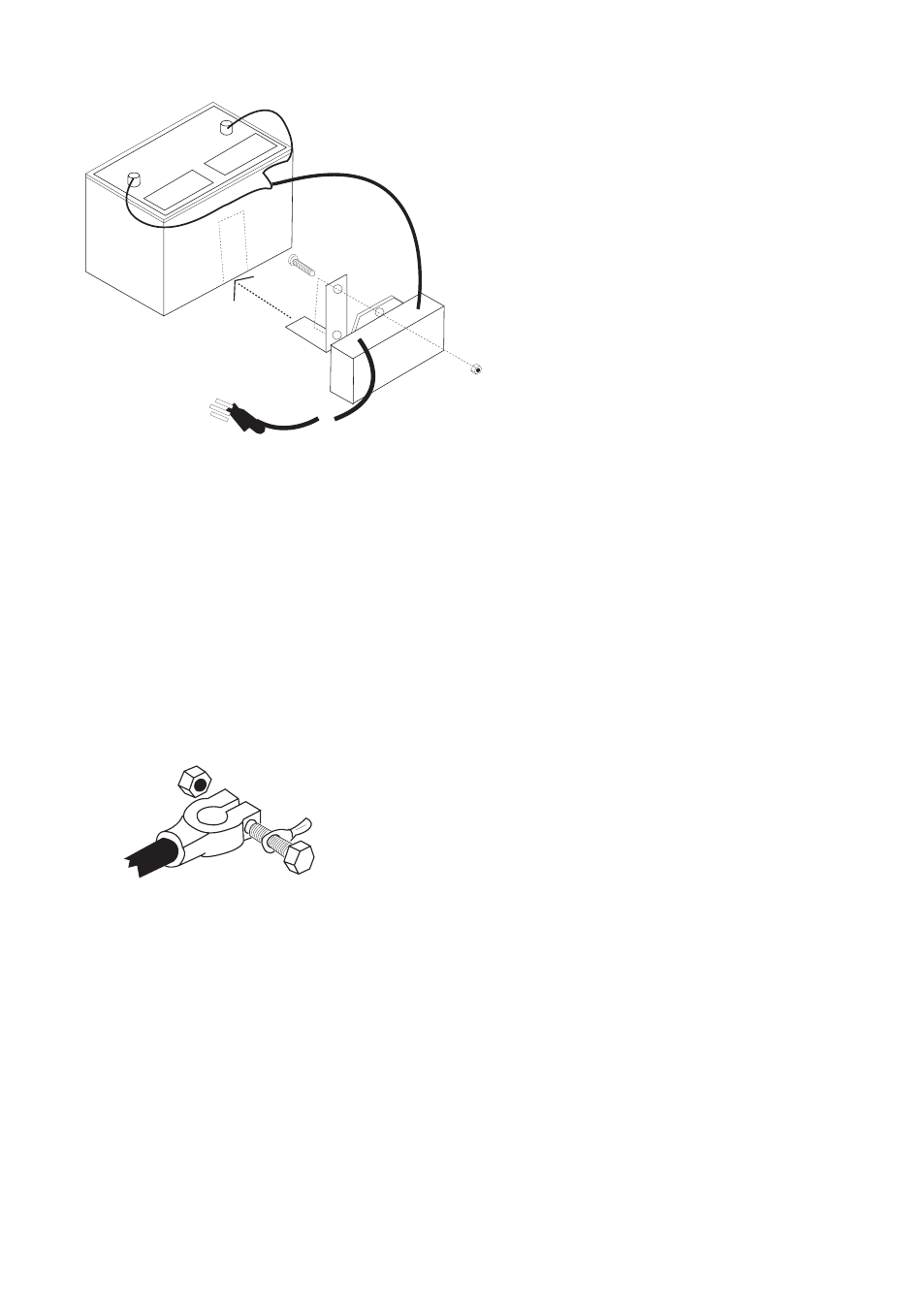
1. Fasten the supplied mounting
bracket to the charger with the
provided hardware as illustrated
in Figure 1.
2. Slide the bottom flange of
the mounting bracket under the
battery. The battery weight will
hold the charger in place.
3. Check polarity of battery posts.
Positive (POS, P, +) battery post
usually has larger diameter than Negative (NEG, N, –) post. Determine
which battery post is grounded (connected) to the chassis. If Negative post
is grounded to chassis (as in most vehicles), see step a. If Positive post is
grounded to the chassis, see step b.
a) For negative-grounded vehicle, connect Positive (
RED
) lug from charger
to Positive (POS, P, +) ungrounded battery post. Connect Negative (BLACK)
lug to vehicle chassis or engine block, away
from battery. Do not connect lug to carburetor,
fuel lines, or sheet metal body parts. Make the
connection to a heavy gauge metal part of the
frame or engine block.
b) If you have a positive ground system in your
vehicle, you must mark the two DC output cable
conductors with the color currently on each lug
and remove the attached battery lugs. Switch
the lugs with new lugs of the same size but on
opposite conductors. Put the new, larger lug on
the conductor that is black (must remain identified as black or negative) and
the new smaller lug on the conductor that is red (must remain identified as
red or positive). The larger lug always connects to the battery and the smaller
lug connects to the engine block or chassis, away from the battery.
For positive-grounded vehicle, connect Negative (
BLACK) clip from charger
to Negative (NEG, N, –) ungrounded post of battery (see
MOUNTING
Figure 1. Charger
Mounting
Figure 2. Terminal
Connections