BVA Hydraulics PA600, PA600H, PA1500, PA1500A, PA1500B, PA2000, PA3801 User Manual
Page 4
BEFORE USE AND SET UP
1. Familiarize yourself with the specifications and illustrations
in this owners manual. Know your pump, its limitations
and how it operates before attempting to use. Refer to
specification chart on page 3 for details of oil port thread
size, usable oil capacity, and more. If in doubt, contact BVA
Hydraulics Technical Service (888) 332-6419.
2.
For models PA1500, PA1500A, PA1500B, PA2000 &
PA3801: Replace shipping plug (red color) with air vent
plug (black color) before use.
3.
Air Connection: Remove plastic cap, connect suitable air
supply to air input port. Air input port is designed to fit the
popular 1/4" NPT air nipple (not included). Ensure that
your air source can dedicate 7.8CFM @ 110~175 PSI to
each pump operated.
4.
Hydraulic Connection: Clean all areas around the oil port
of pump and cylinder. Inspect all threads and fitting for
signs of wear or damage and replace as needed. Clean all
hose ends, couplers and union ends. Remove the manifold
plug, then connect oil output port to suitable fittings and
application/cylinder.
NOTICE: Always secure threaded port connections with high
grade, non-hardening pipe thread sealant. Teflon tape can
be used if only one layer of tape is used and it is applied
carefully, two threads back, to prevent the tape from being
introduced into hydraulic system, which could cause jamming
of precision-fit parts.
WARNING: To reduce the risk of personal injury and/
or property damage, Hydraulic connections must be
securely fastened before building pressure in the system.
Release all system pressure before loosening any
hydraulic connection in the system.
OPERATION
WARNING: Always monitor pressure, load or position
using suitable equipment. Pressure may be monitored by
means of an optional manifold and gauge. Load may be
monitored by means of a load cell and digital indicator.
4
Correct application position can only be determined by
the operator of the equipment.
For Model PA600H: (Hand Button Pump)
1. To extend the cylinder:
a. Close release valve by turning it clockwise firmly.
b. Depress the hand button on top of the air input port
until desired pressure, load or position is reached.
2. To hold the cylinder in position, simply release the hand
button to deactivate the pump.
3. To retract cylinder, open release valve by turning it counter-
clockwise slowly.
For Models PA600, PA1500, PA1500B, PA2000 & PA3801:
1. To extend the cylinder, depress on the foot pedal marked
"Pump" (horizontal portion) until desired pressure, load or
position is reached.
2. To hold the cylinder in position, release the foot pedal to
deactivate the pump.
3. To retract the cylinder, depress the release valve by stepping
on the foot pedal marked "Release" (raised, stirrup shaped
portion).
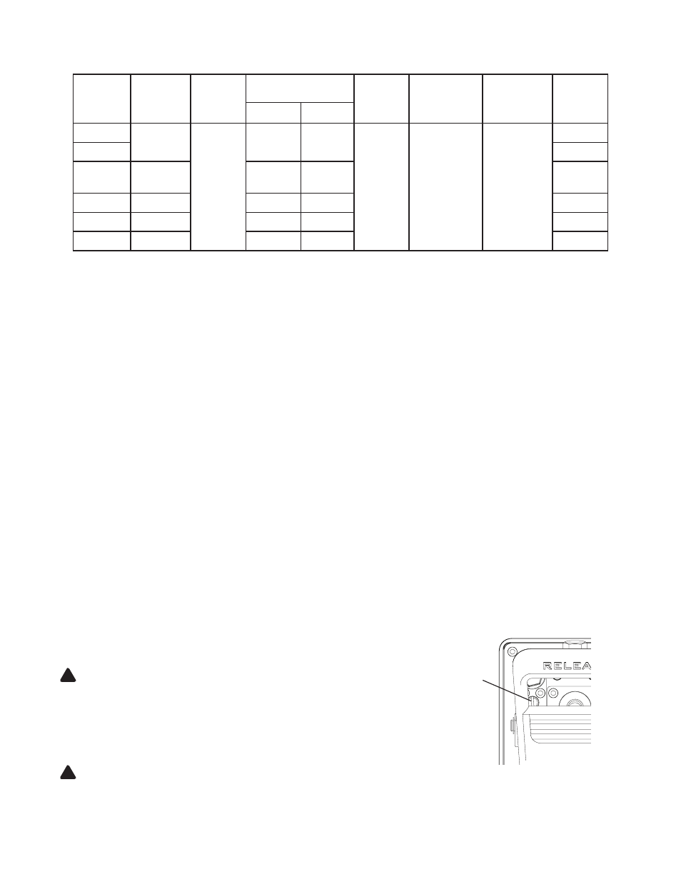
For Model PA1500A:
1. Install in-line pressure gauge between air pump and
cylinder.
2. Loosen External Pressure Relief Adjustment Screw fully.
3. Begin pumping air while monitoring pressure gauge. Tighten
Adjustment Screw (approximately 1/4 turn increments) until
gauge reaches desired working pressure.
NOTICE: Never operate a pump which is disconnected
from application. If operate in this condition, the hose and
connections will become pressurized. This increases burst
hazard. Damage may occur to pump and its components.
!
!
SPECIFICATIONS
Model
Number
Usable Oil
Capacity
(in
3
)
Rated
Pressure
(psi)
Output Flow Rate
(in
3
/min)
Input Air
Pressure
(psi)
Output Port
Thread
(Oil)
Input Port
Threads
(Air)
Weight
(lbs w/
fluid)
No Load
Load
PA600
36.6
10,000
61
9
110 - 175 3/8” -18NPTF 1/4” - 18NPT
14.1
PA600H
12.7
PA1500,
PA1500B
91.5
66
11
18.1
PA1500A
91.5
61
11
18.7
PA2000
122
65
12
20.1
PA3801
231.9
65
12
26.4
External Pressure Relief
Adjustment Screw