Brickcom OB-v2-series User Manual
Page 22
19
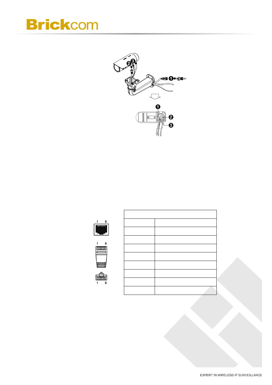
C. DIDO, Audio In/Out, RS485, and Antenna Connection
a. PoE Connection
For the Power over Ethernet connection, construct the PoE cable
using the pin definitions of the RJ45 connector below and refer to
step 5 for instructions on how to install the Water Proof Connector.
Once the PoE cable has been constructed using the waterproof
connector, pass the RJ-45 cable from the camera through the bracket
and connect it to the PoE cable.
RJ45 Connector 1
Pin No.
Function
Pin 1
Transmit Out+ (Tx+)
Pin 2
Transmit Out- (Tx-)
Pin 3
Receive In+ (Rx+)
Pin 4
DC 48V
Pin 5
DC 48V
Pin 6
Receive In- (Rx-)
Pin 7
48V_GND
Pin 8
48V_GND