Baldwin Ashton Two-Point Lock Handleset User Manual
Page 3
© 2005 BALDWIN HARDWARE CORPORATION, READING, PA, U.S.A.
H1705.000.00015A
13
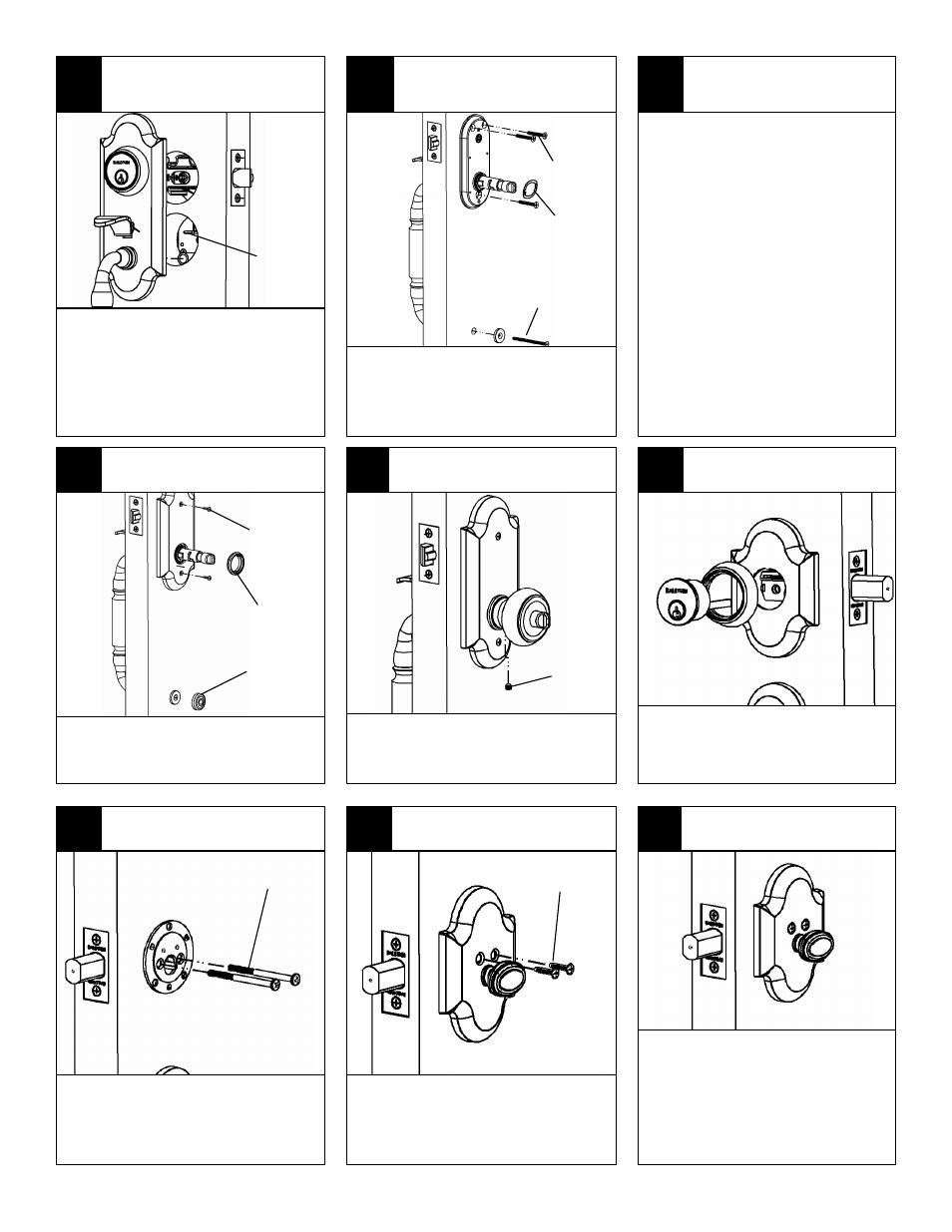
INSTALL INTERIOR PLATE &
SCREW COVER
15
INSTALL KNOB / LEVER
16
INSTALL DEADBOLT
12
CHECK ALIGNMENT & TEST
OPERATION
Check alignment of exterior assembly with
door edge.
Test Operation:
A) Operate thumbpiece to retract latch
B) Temporarily place knob / lever over
interior assembly to operate latch
C) Push in & rotate turn button to lock
thumbpiece.
D) Insert key to test cylinder and retract
latch.
E) Unlock turn button and remove knob or
lever
Note: If operation is binding / not smooth,
loosen thru-bolting & do the following:
A) Check tailpiece to spindle alignment
B) Check spindle to latch alignment
C) Realign interior and exterior
assemblies to door edge.
D) Retighten thru-bolting
Install interior plate and thread thimble onto
housing. Tighten with supplied tool. Secure
interior plate with (2) #6 screws to interior
mechanism. Install screw cover.
Place mounting plate over tailpiece. Insert
(2) #10-32 x 2-5/8” long screws through
plate, deadbolt assembly and into cylinder.
Orient exterior plate properly. Tighten
screws.
Slide knob or lever onto the mechanism
housing. Tighten ¼” set screw with supplied
allen wrench. Operate knob / lever, turn
button, thumbpiece & cylinder.
Place interior deadbolt assembly over
tailpiece. Secure with (2) #8-32 x 3/4”
screws.
Operate turnpiece & cylinder to retract
and throw deadbolt.
Note: If binding occurs do the following.
A) Remove interior deadbolt assembly
B) Loosen screws and adjust alignment
C) Retighten screws
D) Reinstall interior deadbolt assembly
14
INSTALL MOUNTING PLATE
Install (3) #10-32 screws through interior
assembly into exterior assembly screw
posts. DO NOT OVERTIGHTEN. Ensure
wave washer is installed over subassembly.
Install bottom door pull thru-bolt.
11
INSTALL SCREWS
17
INSTALL DEADBOLT INTERIOR
ASSEMBLY
18
TEST DEADBOLT OPERATION
10
INSTALL EXTERIOR ASSEMBLY
Install exterior assembly.
A) Turn tailpiece vertical
B) Insert cylinder tailpiece into spindle
C) Align screw posts with interior
mechanism body.
D) Engage thumbpiece with interior
mechanism. Thumbpiece arm must be
under tab of interior mechanism.
TAB FOR
THUMBPIECE
ENGAGEMENT
#10-32 x 2-1/2”
SCREW
#10-32 X 1-1/4”
SCREWS
#6-32 x 7/16”
SCREWS
THIMBLE
(MAY BE
PREASSEMBLED)
SCREW
COVER
¼” SET
SCREW
Make sure deadbolt is thrown.
Slide cylinder assembly through the
cylinder ring and collar. Insert tailpiece
through hub in deadbolt assembly.
#10-32 x 2-5/8”
SCREWS
#8-32 x 3/4”
SCREWS
WAVE
WASHER