External control and programming – B&K Precision 9180 Series - Datasheet User Manual
Page 3
www.bkprecision.com
Programmable Dual-Range DC Power Supplies
9170 & 9180 series
3
External control and programming
Versatile connectivity
These power supplies offer SCPI IEEE488.2 compatible standard USB, optional
GPIB and LAN interfaces, and an optional 8-bit digital I/O and analog control
card to facilitate test system development and integration.
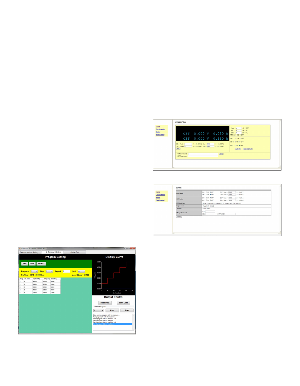
Application software
Create test sequences for execution in list mode via the GPIB or USB interface
using the included PC software.
■
Create, save, and load program lists
■
View output characteristic curves and export data to a file
■
Pass/Fail test monitors maximum and minimum voltage and current values
over a specified period of time
Test sequence execution in list mode
The list mode feature allows users to download a list of commands to the
power supply’s internal memory and execute them. A total of 150 steps can
be allocated to one of 10 internal memory locations. The test sequence can be
programmed remotely through the included application software or via the USB,
GPIB, or LAN interfaces using SCPI commands. Each step’s voltage, current,
and duration parameters can be set, with sequences configured for single or
repeated execution.
Telnet interface
(2)
Power supplies can be controlled with SCPI commands via a Telnet connection
over the Ethernet interface. Any computer with a Telnet client can be used to
control the power supply.
Web server interface
(2)
The 9170/9180 series power supplies with the GPIB/LAN interface installed
provide a built-in Web server that allows users to configure, control, or monitor
the basic settings of the power supply from a remote computer using a Java-
enabled Web browser. Connect to the user-defined IP address to view the web
control page. SCPI commands can also be sent through the Web server interface.
Interface for controlling voltage, current, and output state
Control settings page for configuration of protection
and password settings for the system
External analog programming interface
(1)
The power supplies’ output voltage and current can be controlled by either
external analog voltage or resistance. Use a 0-5 V or 0-10 V external DC
voltage source, or 0-5 kΩ variable resistor to control the output from zero to
full scale.
Multi-unit control
(3)
In multi-unit control mode, up to 31 units can be daisy chained via the RS485
interface for synchronization purposes and controlled from one master unit via
the USB, GPIB, or LAN interface.
(1) Requires card option DR1DIO or DR2DIO
(2) Requires card option DRGL
(3) Requires card option DRRS485