Controls and indicators – B&K Precision 1730A - Manual User Manual
Page 9
8
CONTROLS AND INDICATORS
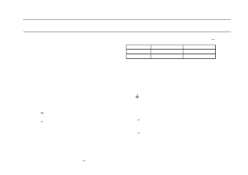
current range: value is read on bottom meter scale of A meter.
RANGE
MODEL 1730A
MODEL 1710A
High
0 to 3A
0 to 1A
Low
0 to 0.5A
0 to 0.25A
POWER CONTROLS
7. ON-OFF Switch.
OUTPUT TERMINALS
8. “+” Terminal (Red). Positive polarity output terminal.
9.
Terminal (Green). Earth and chassis ground.
10. “-” Terminal (Black). Negative polarity output terminal.
METERS
11. A Meter. Reads output current in amperes. Use top scale
when High-Low switch is set to High, bottom scale
when switch is set to Low.
12. V Meter. Reads output voltage on 0 to 32V scale.
REAR PANEL CONTROLS
13. Fuse.
14. Power Cord.
15.
110/220 Line Voltage Conversion Switch.
INDICATORS
Either the “CC” or “CV” indicator will be lighted whenever
the unit is operating, thus serving as a pilot light. The unit
automatically changes from CV to CC operation when the preset
current limit is reached.
1. C.C. (Constant Current) Indicator. Red LED lights in
constant current mode. Unit regulates output current at
value set by CURRENT controls.
2. C.V. (Constant Voltage) Indicator. Green LED lights in
constant voltage mode. Unit regulates output voltage at
value set by VOLTAGE controls.
VOLTAGE CONTROLS
3. Coarse Control. Coarse adjustment of output voltage. Read
value on V meter.
4. Fine Control. Fine adjustment of output voltage. Read
value on V meter.
CURRENT CONTROLS
5. CURRENT Control. Adjusts current limit in constant
voltage mode. Adjusts constant current value in constant
current mode. Range of adjustment is determined by High-
Low switch.
6.
High-Low Switch. High position selects high current range;
value is read on top meter scale of A meter. Low position
selects low