Controls and indicators, Front panel, 4controls and indicators – B&K Precision 1673 - Manual User Manual
Page 9: 1 front panel
7
4
Controls and Indicators
4.1
Front Panel
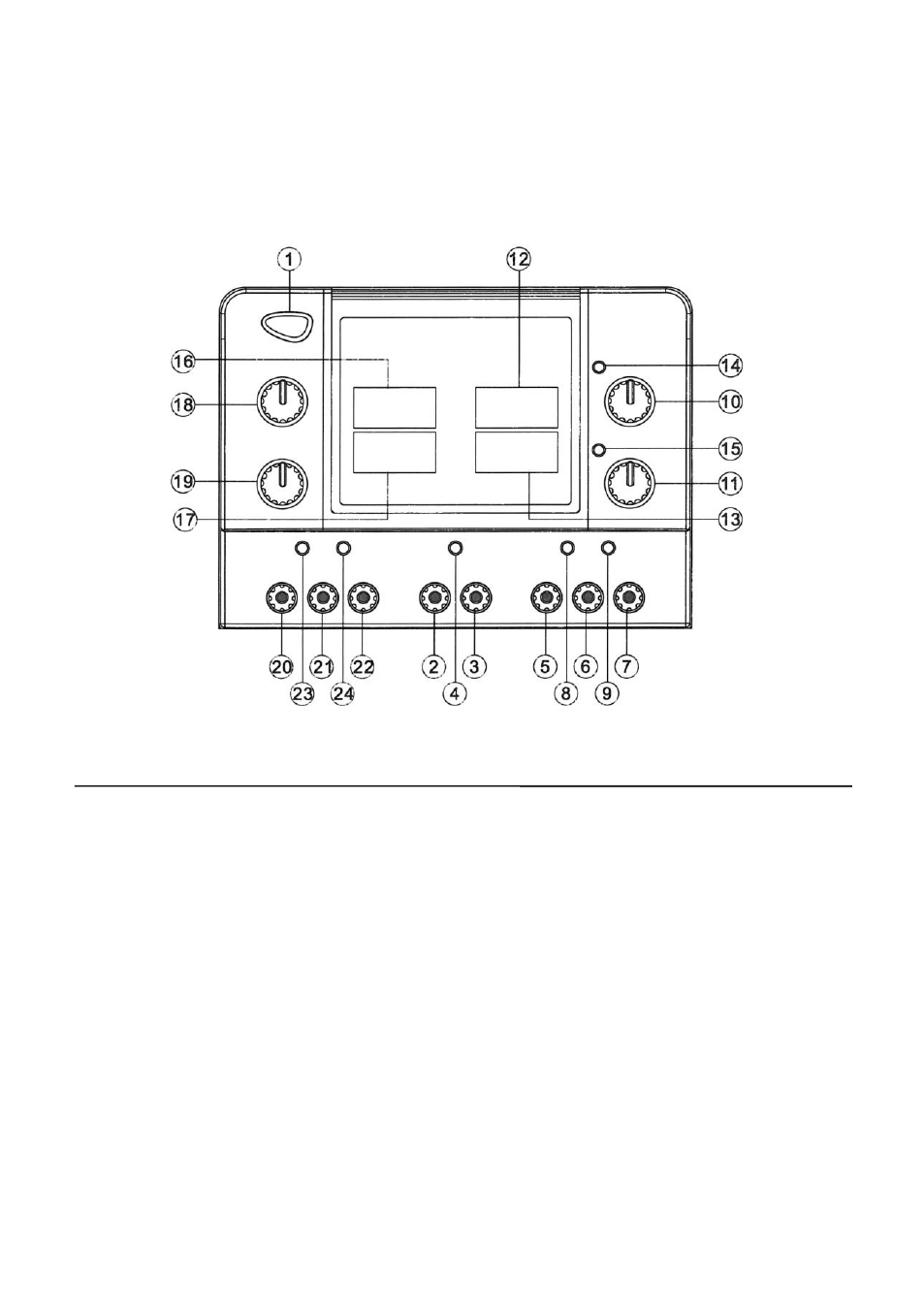
Figure 2 – Front Panel
1) Power switch
2) Negative output terminal of the fixed 5V/3A output
3) Positive output terminal of the fixed 5V/3A output
4) Overload indicator LED for fixed 5V/3A output
5) Negative output terminal of the master output
6) Ground terminal of the master output
7) Positive output terminal of the master output
8) CC mode LED for the master to indicate constant current
9) CV mode LED for the master to indicate constant voltage
10) Master voltage adjustment knob with push/pull switch mechanism for series tracking
mode operation
11) Master current adjustment knob with push/pull switch mechanism for parallel mode
operation
12) Master voltage indicator display (3-digit green 0.56” LED)
13) Master current indicator display (3-digit red 0.56” LED)
14) Series mode indicator LED