B&K Precision 1762 - Manual User Manual
Page 13
13
CONTROLS AND INDICATORS
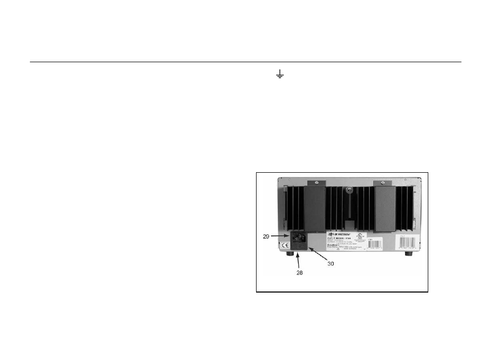
Fig. 2. Rear Panel Controls.
25. Coarse VOLTAGE Control. Coarse adjustment of the output
voltage of the “B” supply when the INDEPendent mode is
selected. Also sets the 5% to 100% tracking in the SERies
TRACKing mode. Disabled in the PARallel TRACKing mode.
Read the value on the “B” LED Display when the voltage (V)
metering mode is selected.
26. Fine VOLTAGE Control. Fine adjustment of output voltage of
the “B” supply when the INDEPendent mode is selected. Also
sets the 5% to 100% tracking in the SERies TRACKing mode.
Disabled in the PARallel TRACKing mode. Read the value on
the “B” LED Display when the voltage (V) metering mode is
selected.
27. CURRENT Control. Adjusts current limit of “B” supply in
constant voltage mode. Adjusts current value of “B” supply in
constant current mode. Current can be read from the “B” LED
Display when the current (A) metering mode is selected.
28. Left V/A Switch. Selects current or voltage metering mode for
the 0-30 V “B” supply. When in the A (amps) position (in),
current is read form the “B” LED Display. When in the V
(volts) position (out), voltage is read form the “B” LED
Display.
29. “B” LED Display. Digital display indicates voltage or current
at the 0-30 V “B” supply (depending on the setting of the A/V
switch).
30. “+” Terminal (Red). Positive polarity output terminal for the
“B” supply. In series tracking operation, this terminal is
connected to the negative terminal of the “A” supply.
20. Terminal (Green). Earth and Chassis Ground.
21. “-” Terminal (Black). Negative polarity output terminal
for the “B” supply. Also serves as the negative polarity
terminal for 0-to-60 V series tracking operation.
REAR PANEL CONTROLS
22. Fuse
23. Power Cord
24. 110/220 Line Voltage Conversion Switch