Hanger bracket hole location – Anemostat HCR User Manual
Page 6
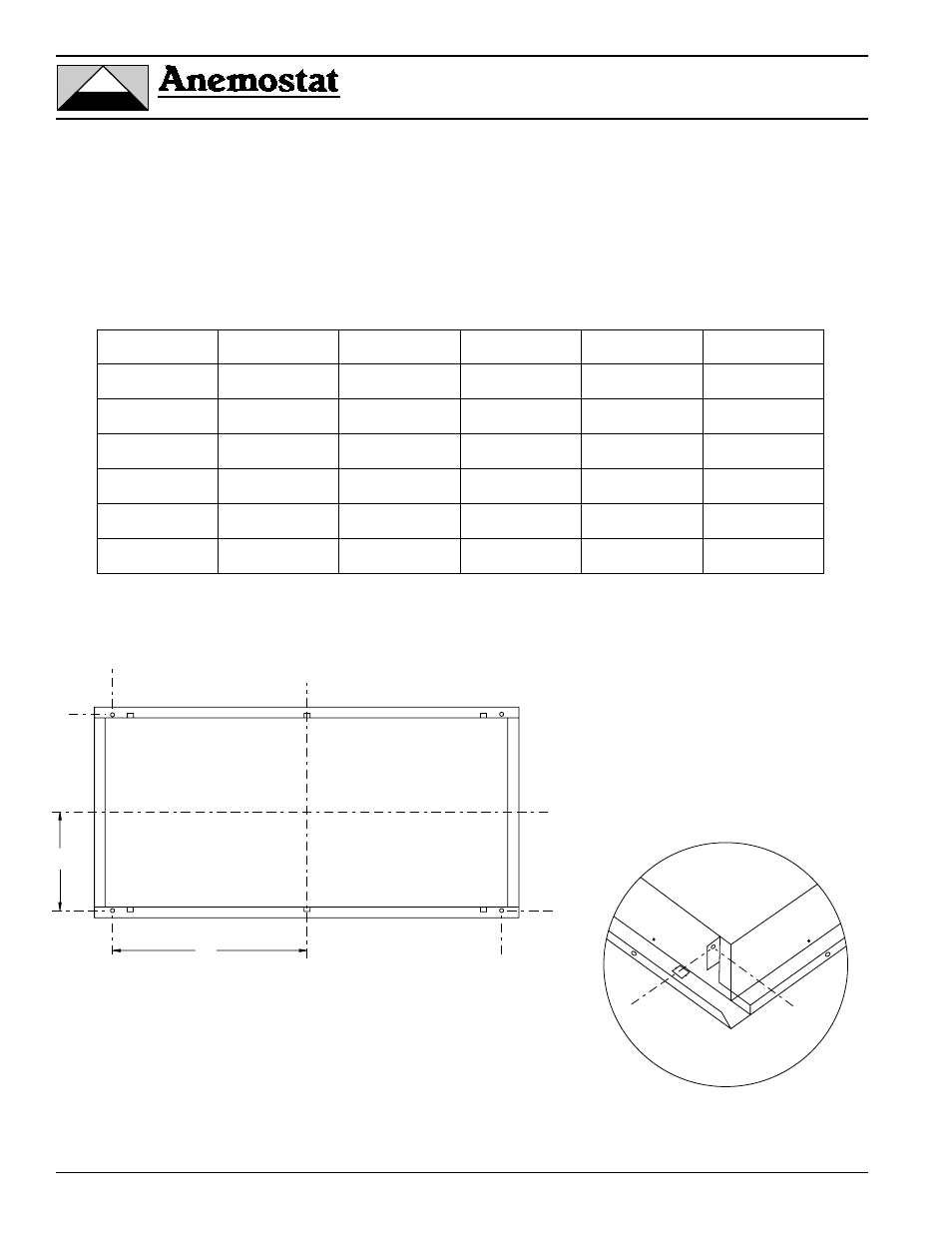
Hanger Bracket Hole Location
For the location of the integral hanger bracket holes on the Multi-Vent panels, see the table and drawing below.
The X & Y dimensions reference the distances from the center of the frame body (which is typically the center of the top
supply air inlet collar) to the center of the hole on the hanger bracket, in the plan view.
6
A M
A M E S T E K C O M
E S T E K C O M P A N Y
P A N Y
®
®
1220 Watson Center Road • Carson, CA 90745
Tel: (310) 835-7500 • Fax: (310) 835-0448
Y
X
C
L
C
L
C L
C
L
MV Size
X
Y
MV Size
X
Y
12 x 48
21-15/16
5-1/16
24 x 60
27-15/16
11-1/16
12 x 60
27-15/16
5-1/16
24 x 72
33-15/16
11-1/16
12 x 72
33-15/16
5-1/16
36 x 36
15-15/16
17-1/16
24 x 24
9-15/16
11-1/16
36 x 48
21-15/16
17-1/16
24 x 36
15-15/16
11-1/16
36 x 60
27-15/16
17-1/16
24 x 48
21-15/16
11-1/16
36 x 72
33-15/16
17-1/16