Controller i/o connections, Analog inputs, 6 controller i/o connections – Alpha Technologies CXPS 48-2T 48V Pos Gnd User Manual
Page 34
Argus Technologies Ltd.
053-393-C0 Rev A WC
Printed in Canada. © 2007 Argus Technologies Ltd. ARGUS and CORDEX are trademarks of Argus Technologies Ltd. All Rights Reserved.
Page 24 of 32
5.6 Controller
I/O
Connections
WARNING
Ensure that input power and output power is removed before attempting work on the CXC’s wiring
connections.
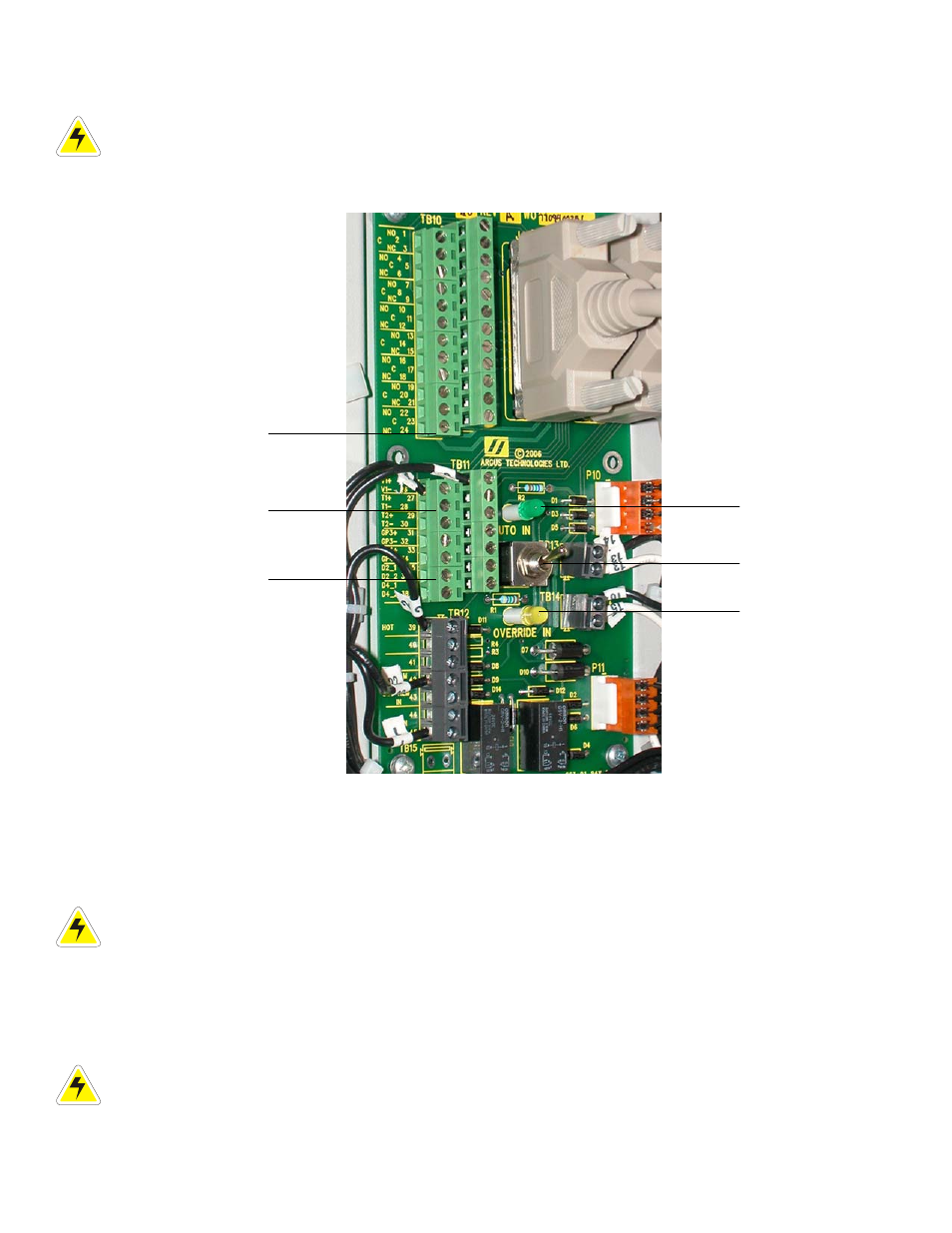
System integration cabling is utilized to bring the controller I/O connections to the front (left side) of the distribution
center:
Figure 13–Controller I/O connections and LVD control card
(illustration only and may not match your installation)
Relay outputs
AUTO IN (green) LED
Analog inputs
LVD control switch
Digital inputs
OVERRIDE IN or Inhibit
(amber) LED
5.6.1 Analog
Inputs
WARNING
Ensure the correct polarity is used for all input cable terminations.
The analog input channels are used to monitor various types of electrical signals. Some of the analog channels
are reserved for specific signals, while others are designated as general-purpose inputs, which accommodate
various types of analog signals. The input cables should be bundled together and routed through the entry holes,
if applicable.
Default configurations and terminal numbers described below have been summarized in the
foldout drawings located at the rear of this manual.
CAUTION: to reduce risk of fire, use only 0.129mm
2
(#26 AWG) or larger wire.