Warning, Battery installation / replacement procedure, Fpr1207-f controls and indicators – Alpha Technologies FlexPoint FPR1207-F - Quick Start Guide User Manual
Page 2
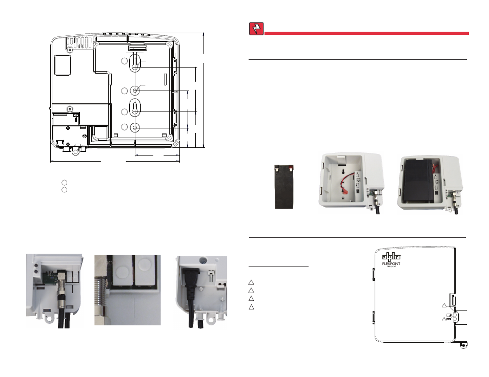
Battery Installation / Replacement Procedure
1. (Failed Battery Replacement) For units with Alpha part number 010-344-20-001 (note that the fi nal
three digits in bold are the key indicator), disconnect the AC line cord from the AC power outlet before
beginning battery replacement.
2. (Battery Replacement / Failed Battery Replacement) Disconnect the wire harness to the battery.
3. Connect the wire harness to the charged battery (a fully charged battery reads about 13Vdc).
4. Install the battery in the cradle as shown in Fig. 8. The locking tab secures it in place.
5. Replace the battery compartment door. To replace the front cover, align the hinges with the hinge sockets
and press them in with the door perpendicular with the main housing. Rotate the door closed until the
closure door latches.
6. Plug the FPR1207-F into an AC power outlet. The Green LED should light.
7. Verify the unit is functioning properly by unplugging the unit. The alarm should sound for one second and
the Green LED should fl ash. The unit will be running on standby battery power.
8. Re-plug the FPR1207-F into an AC power outlet. The unit is ready to be placed into service.
Fig. 6, 7.2Ah Battery
2
Fig. 2, FPR1207-F Dimensions (in/mm)
(Viewed From Back)
3
Risk of explosion if battery is replaced by an incorrect type. Recycle spent batteries in
accordance with local regulations.
WARNING!
7.8"
198mm
3.0"
76mm
2.5"
63.5mm
2.4"
61mm
3.0"
76mm
1.3"
33mm
8.7"
221mm
1
1
2
2
Ш.380"
.200"
Ш.250"
Mounting holes for customer-supplied #12 hardware or equivalent
"Keyhole" slots for easy mounting
1
2
Fig. 3, RF Cable Connection
Fig. 5, AC Power Cord Connection
(Viewed From Back)
Fig. 7, Battery Compartment,
With Wire Harness
R
Remove cover to access
silence alarm and battery
emergency use buttons.
FPR1207-F Controls and Indicators
VISUAL STATUS INDICATORS
1
Green LED:
AC mode
Green LED fl ashing: Battery mode
Red LED:
Replace battery
Red LED fl ashing:
Battery missing / Low battery
2
1
2
1
Fig. 8, Battery
Installed
010-344-B0-001 Rev. B (2/2014)
010-344-B0-001 Rev. B (2/2014)
Silence Alarm
Battery Emergency Use
Silence
Alarm
Battery
Emergency
Use
Fig. 4, Push Button Detail
2