Gorman-Rupp Pumps PA6C60C-F4L 1504811 and up User Manual
Page 44
PA SERIES
OM-05768
MAINTENANCE & REPAIR
PAGE E - 22
Lubricate the bearings as indicated in LUBRICA
TION at the end of this section.
Securing Bearing Housing And Drive Assembly
To Engine
(Figure 4)
Install the key (30 Figure 5) in the shaft keyway,
making sure to leave room in the keyway for the
drive key (31, Figure 5). Install the bushing (10) and
sheave (11) on the shaft to the dimension shown in
Figure 10.
Figure 10. Compressor Drive Sprocket
Positioning
NOTE
When properly installed to the dimension shown in
Figure 10, the key (30, Figure 3) will not extend fully
through the bushing. This is an acceptable fit for
this application.
Secure the bushing and sheave to the shaft by
torqueing the bushing screws to 23 ft. lbs. (280 in.
lbs. or 3,2 m. kg.) max. Install the belt (9) over the
sheave and up through the slot in the mounting
flange (9, Figure 5).
(Figure 8)
Install the shaft key (31, Figure 5) in the shaft key
way. Position the flexible portion of the coupling as
sembly (1) on the shaft as shown in Figure 8.
NOTE
The flexible portion of the coupling must be proper
ly positioned on the shaft. The heads of the caps
crews in the center of the coupling must be posi
tioned away from the pump.
Align the keyway in the bushing (2) with the shaft
key, and slide it onto the shaft to the dimension
listed below. Rotate the flexible portion of the cou
pling until the tapped holes for the two setscrews
align with those in the bushing, and install the set
screws.
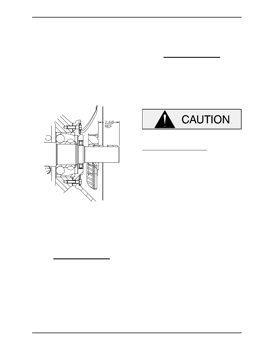
Make certain that the flexible portion of the
coupling is mounted as shown in Figure 8.
This dimension is critical. If the coupling
is not properly positioned on the shaft, the
coupling parts may not fully engage, or a
pre‐load condition can cause premature
bearing failure.
The coupling must be positioned 1.44
inch (37 mm) from the end of the shaft.
This will allow the two portions of the cou
pling to fully engage when the intermediate
is secured to the engine bellhousing, with
out pre‐loading the bearings.
With the flexible portion of the coupling and the
bushing properly positioned on the shaft, tighten
the two setscrews in an alternating sequence until
the bushing and coupling are fully secured. Torque
the setscrews to 23 ft. lbs. (280 in. lbs. or 3 m. kg.).
If the complete coupling assembly is being re
placed, apply `Loctite Retaining Compound No.
242' or equivalent to the threads of the hardware (6
and 7) and secure the outer ring of the coupling to
the engine flywheel by torquing the hardware to 45
ft. lbs. (540 in. lbs. or 6,2 m. kg.).
Using a suitable lifting device, position the as
sembled drive and rotating assembly so the flex
ible portion of the coupling seats inside the outer
ring attached to the engine flywheel.