Gorman-Rupp Pumps PAV3B60C-3TNV70 1433753 and up User Manual
Page 37
OM-06260
PA SERIES
MAINTENANCE & REPAIR
PAGE E - 19
plate over the shaft and secure it to the bearing
housing with the flat head capscrews (4).
To prevent damaging the shaft sleeve O‐ring (36)
on the shaft threads, stretch the O‐ring over a piece
of tubing. The I.D. of the tubing must be slightly
larger than the O.D. of the shaft. To ease installation
the tubing wall should be as thin as possible. The
length should be long enough to cover the threads
on the end of the shaft. Slide the tube over the shaft
threads, then slide the O‐ring off the tube and onto
the shaft. Remove the tube, and continue to slide
the O‐ring down the shaft until it seats against the
shaft shoulder.
Lubricate the external stationary seat O‐ring with
light oil. Slide the seal assembly onto the shaft until
the external stationary seat O‐ring engages the
bore in the seal plate.
Clean and inspect the impeller as described in Im
peller Installation and Adjustment. Install the set
of impeller shims (3) provided with the seal and
install the impeller key (30) in the shaft keyway.
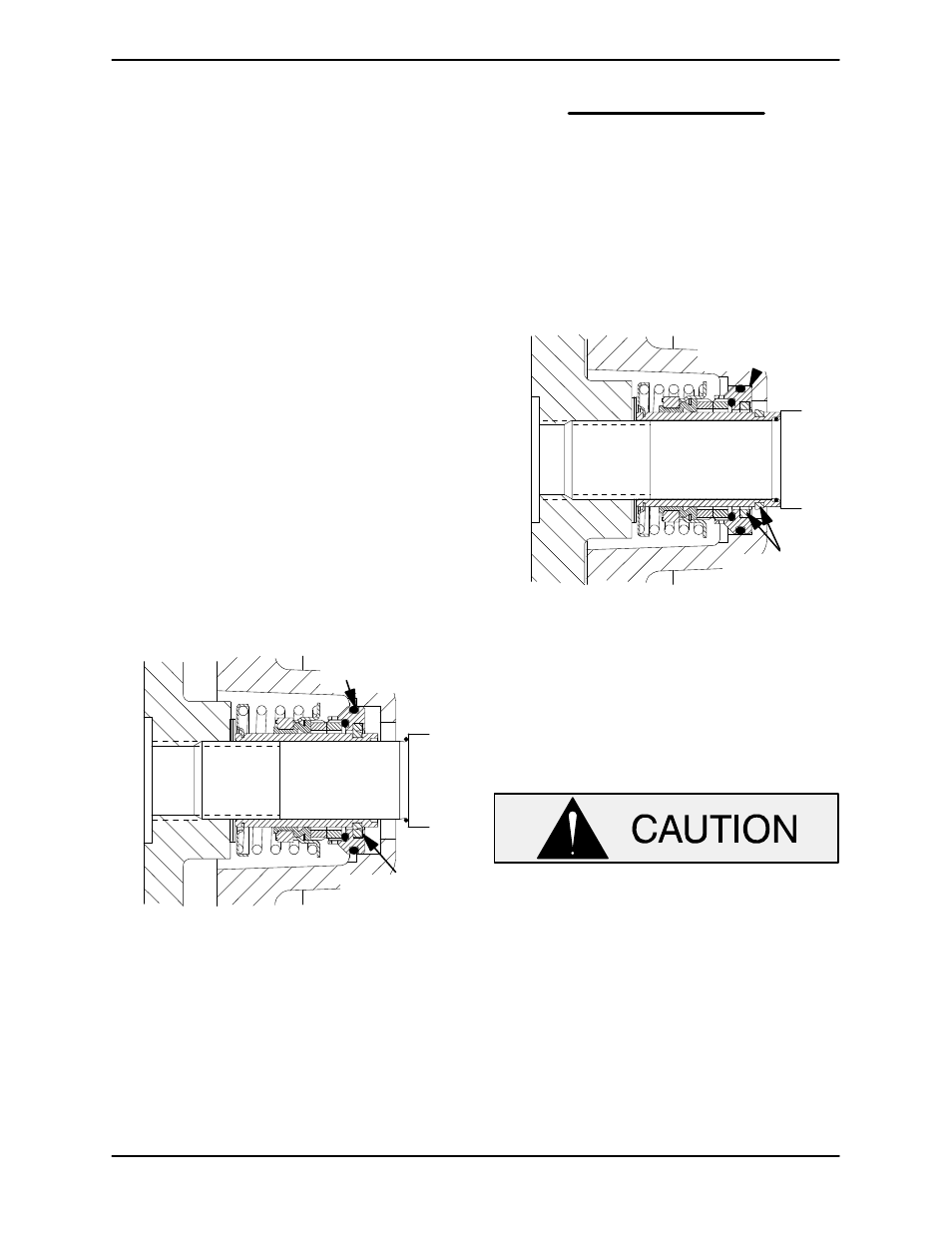
Position the impeller keyway over the impeller key
and press the impeller onto the shaft until it is
seated against the seal (see Figure 9).
O‐RING ENGAGED
WITH SEAL PLATE
BORE
SHEAR RING
(UNSHEARED)
Figure 9. Seal Partially Installed
Install the impeller washer (33). Apply a small
amount of `Never‐Seez' or equivalent anti‐lock
compound on the threads of the impeller screw
(32) and use the impeller screw to press the impel
ler onto the shaft. This action will press the station
ary seat into the seal plate bore.
NOTE
A firm resistance will be felt as the impeller presses
the stationary seat into the seal plate bore.
As the stationary seat becomes fully seated, the
seal spring compresses, and the shaft sleeve will
break the nylon shear ring. This allows the sleeve
to slide down the shaft until seated against the
shaft shoulder. Continue to use the impeller screw
to press the impeller onto the shaft until the impel
ler, shims, and sleeve are fully seated against the
shaft shoulder (see Figure 10).
STATIONARY SEAT
FULLY SEATED IN
SEAL PLATE BORE
SHEAR RING
(SHEARED)
Figure 10. Seal Fully Installed
Torque the impeller screw to 90 ft. lbs. (12,4 m.
kg.).
If necessary to reuse an old seal in an emer
gency, carefully separate the rotating and station
ary seal faces from the bellows retainer and sta
tionary seat.
A new seal assembly should be installed
any time the old seal is removed from the
pump. Wear patterns on the finished faces
cannot be realigned during reassembly.
Reusing an old seal could result in prema
ture failure.
Handle the seal parts with extreme care to prevent
damage. Be careful not to contaminate precision
finished faces; even fingerprints on the faces can
shorten seal life. If necessary, clean the faces with a
non‐oil based solvent and a clean, lint‐free tissue.
Wipe lightly in a concentric pattern to avoid
scratching the faces.