Gorman-Rupp Pumps PA12A60-B-6068H-ESP 1501367 and up User Manual
Page 49
OM-06261
PA SERIES
MAINTENANCE & REPAIR
PAGE E - 29
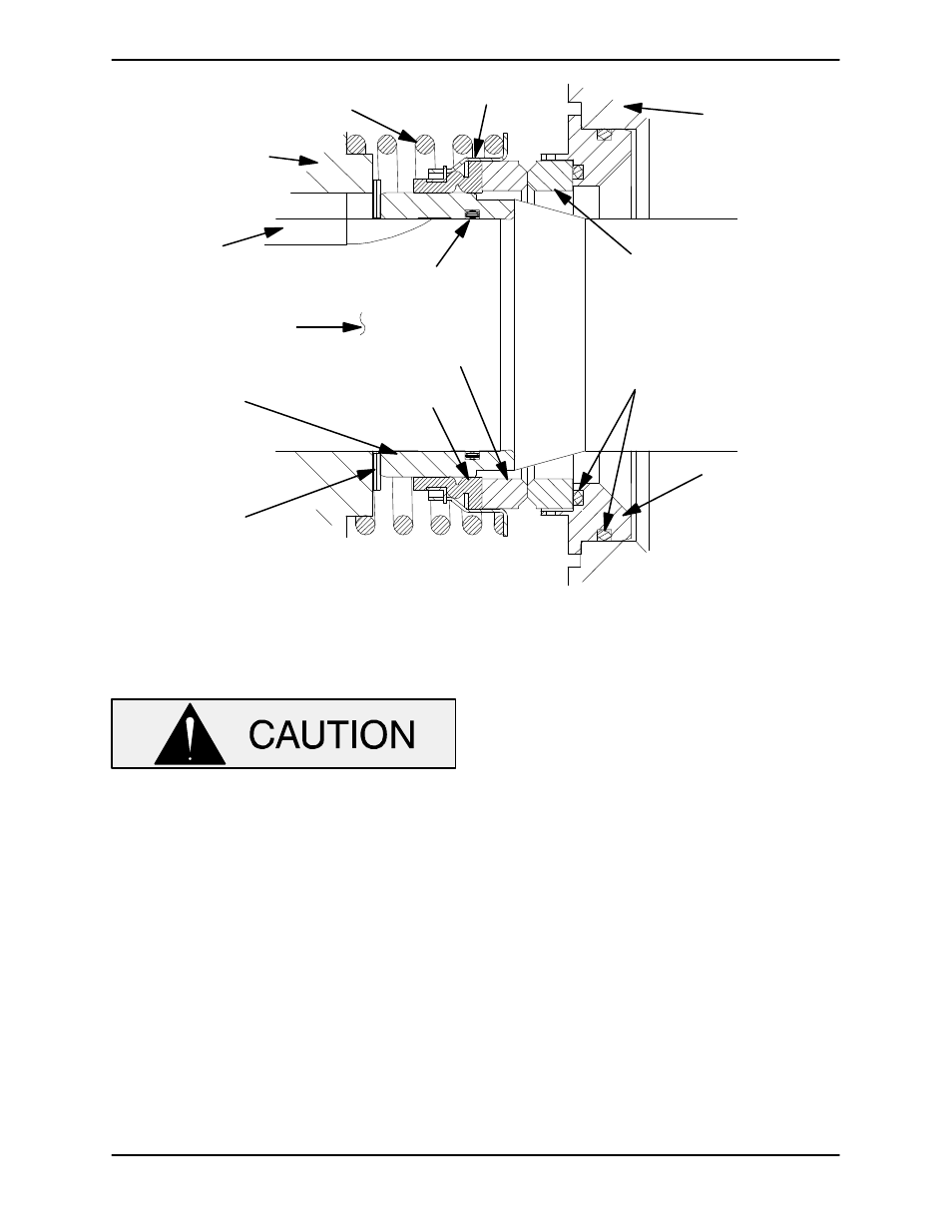
IMPELLER
SHAFT
SPRING
SEAL PLATE
RETAINER
O‐RINGS
BELLOWS
ROTATING
ELEMENT
STATIONARY
SEAT
SLEEVE
O‐RING
IMPELLER
STATIONARY
ELEMENT
SHAFT
SLEEVE
SHAFT
KEY
IMPELLER
SHIMS
Figure 13. Seal Assembly
The standard seal is not designed for oper
ation at temperatures above 160
_F (71_C).
Do not use at higher operating tempera
tures.
Lubricate the outboard stationary seat O‐ring with
water or light oil. Position the seal plate with the im
peller side up and press the stationary subas
sembly (consisting of the stationary seat, O‐rings
and stationary element) into the front of the seal
plate until it seats squarely against the bore shoul
der.
Slide the seal plate and stationary portion of the
seal over the shaft until it is seated against the ped
estal (20). Be careful not to damage the stationary
element or roll or cut the lip of the oil seal (23) on the
shaft keyway. Temporarily secure the seal plate to
the pedestal with three 1/2‐inch by 2‐inch long
capscrews and nuts (not supplied).
Lubricate the seal sleeve O‐ring with a small
amount of light oil and install it in the groove in the
I.D. of the sleeve.
Lubricate the seal sleeve with a small amount of
light oil and slide the rotating subassembly (con
sisting of rotating element, bellows and retainer),
onto the sleeve until the rotating element is just
flush with the turned end of the sleeve.
Slide the sleeve and subassembled seal onto the
shaft until the seal faces contact and the sleeve
seats against the shaft shoulder.
Install the seal spring. Lubricate the seal as indi
cated in LUBRICATION after the impeller, remain
ing pump components, bottle oiler and piping are
installed.