SM Pro Audio EP84: 8 channel microphone preamp User Manual
Page 7
7
Installation - Front Panel Controls
3.4 Audio Connections
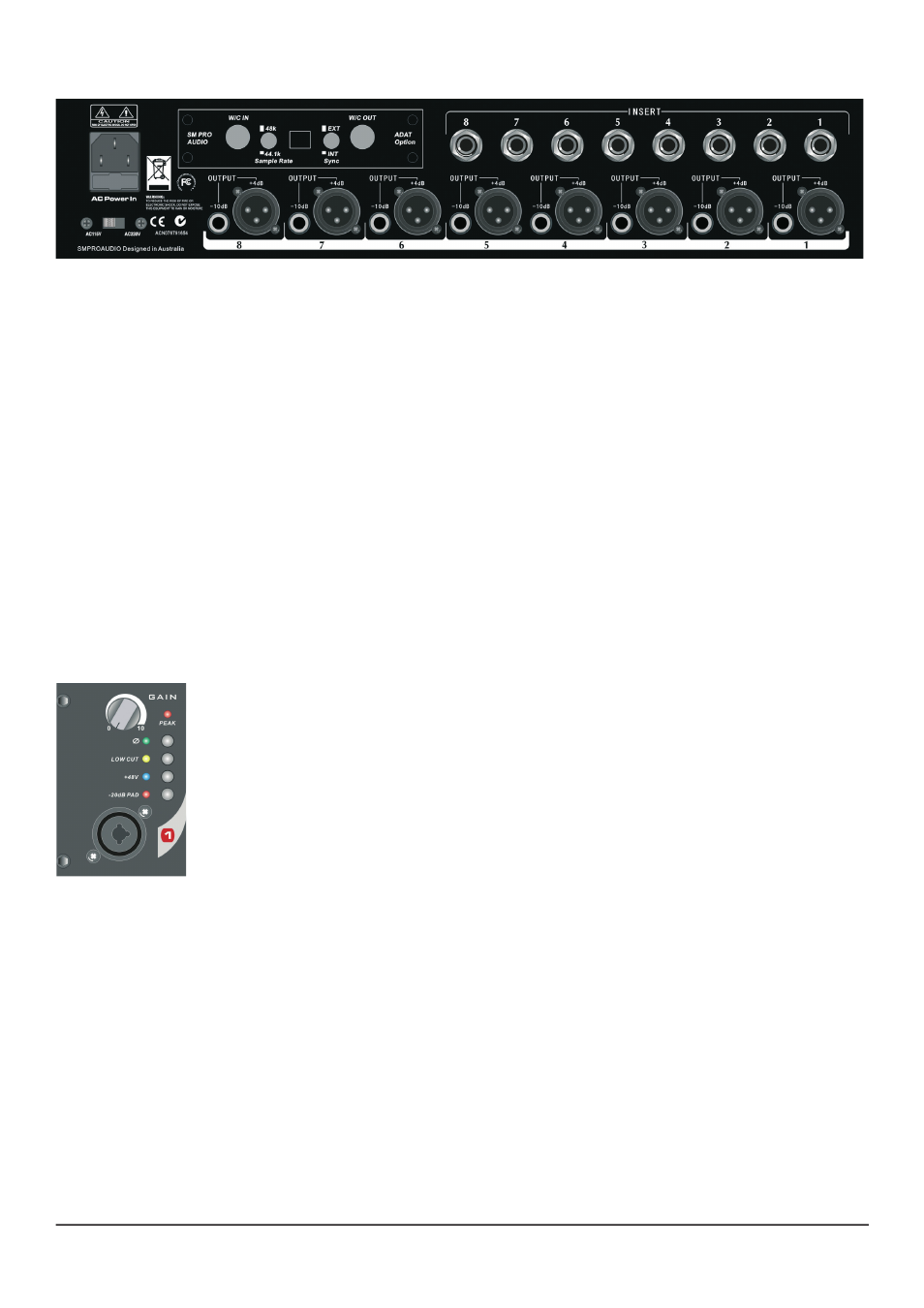
Analog Inputs
8 x combo (XLR & TS) input connectors can be found on the front panel. These are the direct
analog inputs to the EP84’s 8 individual preamplifier modules. Input your audio source material via
either XLR or 1/4” TS cable connectors.
Analog outputs
Both balanced +4dB XLR and unbalanced -10dB 1/4” TS analog output connectors are provided
for each of the eight (8) preamplifier channels. Individual output levels can be controlled via the
associated channels rotary gain control encoder on the front panel.
Insert Points
Each channel of the EP84 features a 1/4” TRS insert connector. Typically, inserts are useful when
integrating additional outboard equipment (noise gates, expanders, compressors, etc.) in-line with
your audio source material. By using a stereo 1/4” TRS audio insert cable you can insert external
devices directly into the signal path of any of the eight audio channels.
4. FRONT PANEL CONTROLS & INDICATORS
4.1 Independent (8x) rotary preamplifier gain controls
Each channel features a rotary gain control for variable adjustment of the desired
pre-amplifier level. 60dB of variable gain is available per channel. Clockwise rota-
tion increases the gain, whereas anti-clockwise rotation decreases the gain.
* Always begin using the EP84 with all gain controls set to the minimum value.
This way you can increase each channel gain gradually to the desired level with-
out experiencing possible unwanted and unexpected loud signal surprises to both
you and the rest of your audio equipment!
4.2 Independent (8x) -20dB PAD switches
A -20dB PAD switch is provided for each channel to allow a twenty (20) decibel gain reduction of the
incoming signal if desired/required. When enabled the corresponding -20dB PAD LED will illuminate.
* This function is useful when connecting extremely „hot“ signals. Excessive signal input levels can
overdrive the EP84’s pre-amplifier input stage resulting in unwanted signal distortion. The PAD
switch allows -20dB of gain attenuation/reduction to compensate for this situation prior to finer pre-
amplifier gain adjustment.
4.3 Independent (8x) phantom power +48v switches
Each channel of the EP84 features a phantom power switch to facilitate enabling or disabling of
48v of continuous power supply to the channel. When enabled the corresponding phantom power
LED will illuminate.
EP84 rear panel