6 description, 1 main parts, 2 connection to air supply – Physio-Control LUCAS User Manual
Page 8: 3 lucas stabilization strap, Escription, Uh t j
8
100057-00 F, ©J
OLIFE
AB 2007
LUCAS
TM
C
HEST
C
OMPRESSION
S
YSTEM
, I
NSTRUCTIONS
FOR
U
SE
u
h
t
j
1.6 D
ESCRIPTION
1.6.1
M
AIN
PARTS
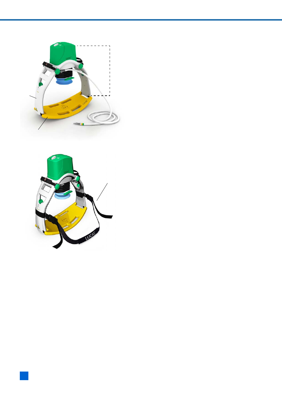
LUCAS consists of an upper part (
h
) and a back
plate (
u
). The back plate is placed underneath the
patient to form a support for the external chest
compressions.
The upper part contains a pneumatically driven
piston rod, which acts on the patient’s chest via a
pressure pad. The pressure pad is surrounded by a
suction cup.
The support legs (
t
) of the upper part are fastened
to the back plate prior to starting compressions.
1.6.2 C
ONNECTION
TO
AIR
SUPPLY
LUCAS is powered by compressed air from a wall
outlet or a cylinder. See Section 6 for specification
of air sources.
The air hose is permanently mounted on LUCAS,
and has a unique male connector at the open end.
A suitable pressure regulator is delivered with
LUCAS.
LUCAS requires no electrical supply and has no
conducting parts on the outside, except the hose
attachment, the claw lock bar, and the upper
attachment of the bellows.
1.6.3
LUCAS S
TABILIZATION
S
TRAP
LUCAS Stabilization Strap (
j
) is an accessory
which is attached to LUCAS to prevent downward
movement of LUCAS during operation. Please see
Appendix B for instructions for use of LUCAS
Stabilization Strap
.