Iv. manual override, V. wiring diagram, Specifications – Spencer Electronic Modulating Bleed Control User Manual
Page 3
The Spencer Turbine Company
600 Day Hill Road Windsor, CT 06095-4706
TEL 800-232-4321
◆
860-688-8361
◆
FAX 860-688-0098
3
IV. Manual Override
The EMBC has a manual override that allows the user to
manually open and close the bleed valve. Use the manual
override to identify the minimum flow set point to avoid
surge and the minimum flow set point necessary to close
the valve without causing "hunting" of the valve. To enter
the manual mode, press both the Up button (10) and the
Down button (7) simultaneously. Both the Amps LED (3)
and the SCFM LED (4) will flash. The digital display (11)
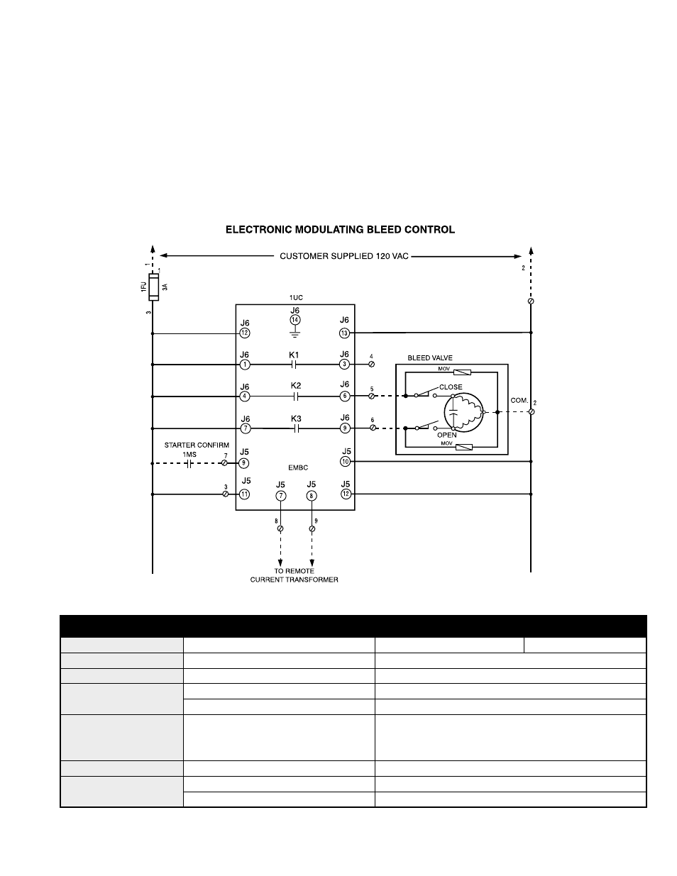
V. Wiring Diagram
Specifications
Dimensions (H x W x D)
Overall 5
1
/
8
x 6
1
/
8
x 3
Cutout 4
3
/
4
x 5
3
/
4
x (n/a)
Part Number CTB 90008
Digital Display
7 Segment / LED
5
/
8
High
Display Amps / SCFM
Power Supply
120/240 VAC, 1Ø, 50/60 Hz
Inputs
Analog (1)
0-5A Current Transformer
Digital (2)
120 VAC (Enable, Reset)
Outputs
(2) Provided Rated @: 5 A General
Valve Open
Purpose, 250 VAC;
1
/
6
HP 120 VAC,
Valve Close
2A Pilot Duty, 120 VAC
Nema Ratings
1, 12, 4, 4X
Note: N-12, 4 and 4X, Indoor Only
Agency Approvals
UL 873
File #E151368, 97ME50259, DD/215K
CUL
CAN/CSA 22.2, No. 24-93
will show motor amps only. Now press the Up button (10) to
manually open the valve or the Down button (7) to manually
close the valve. The corresponding valve LED will illuminate.
To exit the manual mode, press the Reset/Enter "R/E" button
(8). The last display mode will then appear (Amps or SCFM).
Note: If no operator control is initiated for 30 seconds,
the control will revert to automatic.
Note: Dotted lines indicate field wiring.