Extron Electronics SW AV Series Series Setup Guide User Manual
Setup guide — sw av series switchers, Setup guide — sw av series switchers, cont’d, Operation
Setup Guide — SW AV Series Switchers, cont’d
68-644-50
Rev. B 01 10
Step
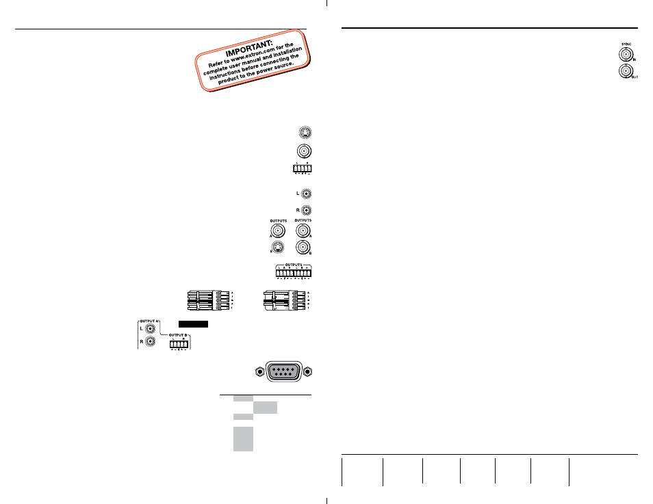
5 — Sync (optional)
• Sync In connector —
Connect an external genlock signal to the Sync In BNC
connector.
•
Sync Out connector — Connect any downstream equipment that requires
genlocking to this BNC connector.
Step
6 — Power
Plug an IEC power cord between the power connector on the switcher and a
100 VAC/240 VAC, 50-60 Hz source. Power on the equipment in the following order:
output device, switcher, contact closure/RS-232 controller, and input devices.
Operation
Select an input
N
Video (auto switching) switchers must be in normal (manual) mode.
1. (Video switchers only)
Press the I/O button to select video, audio, or both to switch.
N
The I/O button has no function on audio-only switchers.
The Audio LED is always lit on audio-only switchers.
2
. Press and release an input button to select that input. That Input LED lights or blinks.
Switch mode (video switchers)
N
Audio breakaway is disabled in auto switch mode.
In auto switch mode, the switcher selects the highest-numbered input with sync signals
present. Toggle auto switch mode on and off as follows:
1.
Press and hold the Mode (Input 1) button.
2.
Press and release either the Auto (Input 3) or Normal (Input 2) button. The Auto Switch
Mode Active LED lights or goes out.
3.
Release the Mode button.
Set an input audio level in the range of -18 dB to +24 dB
N
Video (auto switching) switchers must be in normal (manual) mode.
1. (Switchers with video only)
Press the I/O button to select either video and audio or audio
only. The Audio LED lights.
2.
Press and release an input button to select an input.
3.
Press and hold the Audio Conf/Save button until the Audio Conf/Save LED begins to
blink, then release the button. See the SW AV Series Switchers User’s Manual to read the
audio level display.
4.
Press and release the
>
and
<
buttons to increase and decrease the audio level by 1 dB or
press and hold the button to increase or decrease the level by 3 dB per second.
5.
Press and hold the Audio Conf/Save button until the Audio Conf/Save LED turns off to
save the gain value in memory and exit the audio display and adjustment mode.
Lock and unlock the front panel (executive mode)
Press and hold the Input 2/Normal button and the Input 3/Auto button for approximately
3 seconds. All front panel LEDs flash three times to indicate the mode change.
N
All input LEDs blink once if you attempt a front panel operation while the panel is locked.
Extron
USA - West
Headquarters
+800.633.9876
Inside USA / Canada Only
+1.714.491.1500
+1.714.491.1517 FAX
Extron
USA - East
+800.633.9876
Inside USA / Canada Only
+1.919.863.1794
+1.919.863.1797 FAX
Extron
Europe
+800.3987.6673
Inside Europe Only
+31.33.453.4040
+31.33.453.4050 FAX
Extron
Asia
+800.7339.8766
Inside Asia Only
+65.6383.4400
+65.6383.4664 FAX
Extron
Japan
+81.3.3511.7655
+81.3.3511.7656 FAX
Extron
China
+400.883.1568
Inside China Only
+86.21.3760.1568
+86.21.3760.1566 FAX
Extron
Middle East
+971.4.2991800
+971.4.2991880 FAX
© 2010 Extron Electronics. All rights reserved.
Setup Guide — SW AV Series Switchers
This card provides quick start instructions for an experienced
installer to set up and operate Extron
®
SW AV Series
S-video, composite video, and audio switchers.
Installation
Step 1 — Mounting
Turn off or disconnect all equipment power sources
and mount the switcher as required.
Step 2 — Video and audio inputs
• S-video models —
Connect up to 4, 6, 8, or 12 video inputs to the Input
4-pin mini DIN connectors of the switcher.
• Composite video models —
Connect up to 4, 6, 8, or 12 video input cables
to the Input BNC connectors of the switcher.
• Captive screw connector audio models —
Connect up to 4, 6, 8, or 12 balanced or
unbalanced stereo audio or mono audio devices to the Input 5-pole captive screw
connectors of the switcher.
• RCA connector audio models —
Connect up to 4, 6, 8, or 12 balanced or unbalanced
stereo or mono audio devices to the RCA connectors of the switcher.
Step 3 — Video and audio outputs
• S-video models —
Connect a composite video display to the Output A
or
BNC connector.
Connect an S-video display to the 4-pin mini DIN Output B connector.
• Composite video models —
Connect composite video displays to the
Output A and Output B BNC connectors.
• Captive screw connector audio models —
Connect balanced or unbalanced
stereo audio or mono audio devices to the Output A and Output B 5-pole
captive screw connectors. Wire the connectors as shown below:
• RCA connector audio models —
Connect an unbalanced stereo audio
or mono audio device to the Output A
RCA connectors. Connect
a balanced or unbalanced
stereo audio or mono audio
device to the Output B 5-pole
captive screw connector.
Step 4 — Remote connector (optional)
SW 4 and SW 6 models only —
Connect an RS-232 or IR device OR
a contact closure device, such as a KP 6 Keypad Remote Control.
N
For RS-232 control and IR control, use a cable with
ONLY pins 2, 3, and 5 connected.
For contact closure control, use a cable with pins 2
and 3 NOT connected.
RS-232 communications protocols:
• 9600 baud
• 8 data bits
• 1 stop bit, no parity
• no flow control
For contact closure control, short the pin for the desired input
to pin 5 to select that device. To force an input to be always selected, leave the short in place.
N
For contact closure control, auto switch mode must be off. See “Switch mode (video switchers)“
on the back page.
Contact closure control overrides front panel input selections.
REMOTE
PIN RS-232
Contact
Closure Function
1
—
In #1
Input #1*
Input #2*
Input #3*
Input #4*
Input #5*
Input #6*
2
TX
—
Transmit data
3
RX
—
Receive data
4
—
In #2
5
Gnd
Gnd
Ground
6
—
In #3
7
—
In #4
8
—
In #5
9
* SW 4 and SW 6 models only
—
In #6
For unbalanced audio, connect the sleeve(s)
to the ground contact. DO NOT connect
the sleeve(s) to the negative (-) contacts).
Unbalanced Stereo Output
Ring
Sleeve (s)
Tip
Tip
Ring
Sleeve (s)
Tip
Tip
Balanced Stereo Output
NO GROUND.
NO GROUND.
CAUTION