Setup guide — msw 4v sdi rs, cont’d, Operation — connecting an input to the output, Extron msw 4v sdi rs – Extron Electronics MSW 4V SDI rs Setup Guide User Manual
Page 2: Step 6, Step 1, Step 2, Switcher, The led
Setup Guide — MSW 4V SDI rs, cont’d
Step 6
Power up the input and output devices.
Distribute power to the MSW by
assembling the external power supply
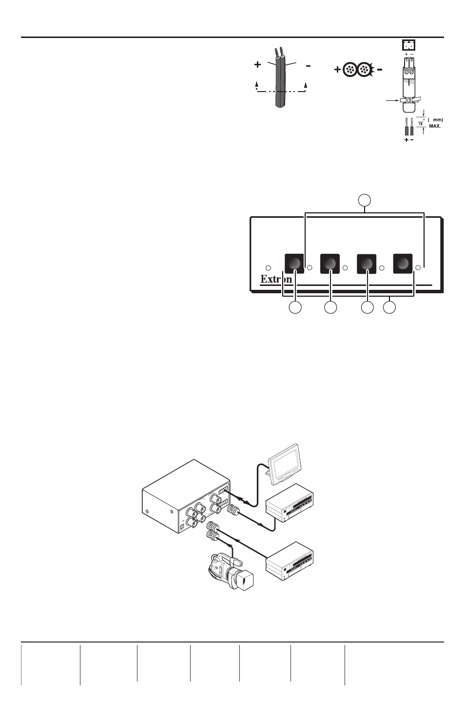
cable (see figure 4) and connecting it to
the power port. Once plugged in, the
mini SDI switcher automatically turns on.
See “Rear Panel Connections” in the
user’s manual for more information.
Operation — Connecting an input to the output
Step 1
Determine the necessary operation
mode for the MSW (the default is
normal). Choose Autoswitch (press
c
and
e
simultaneously) to
automatically switch to the highest
numbered input with active sync pulses.
Choose Normal (press
d
and
e
simultaneously) to manually change the
input. Refer to figure 5 or see “Mode
selection” in the user’s manual for more
information on how to switch between
modes.
Step 2
• If using normal mode, choose the desired input by pressing and releasing its input
button (
b
). The LED (
a
) for the selected input lights.
To switch to a different input, press a different input button.
• If using autoswitch mode, no action is necessary. The mini SDI switcher automatically
switches to the highest-numbered active input.
68-1191-50
Rev. A
08 09
MS
W
4V
SD
I rs
PO
WER
12V
.5A
MA
X
1
2
3
4
CO
NTA
CT
1
2
3
4
A
B
S
D
I
I
N
P
U
T
S
1
2
A
B
S
D
I
O
U
T
P
U
T
S
RS-
232
Tx
Rx
Extron
MSW 4V SDI rs
Switcher
Digital Camcorder
Digital Broadcast
VCR
Digital Broadcast
VCR
Control System
Power Supply
Output
Cord
Captive Screw
Connector
3
5
SECTION A–A
Ridges
Smooth
A
A
Tie Wrap
A/V SWITCHER
MODE
NORMAL
AUTO
AUTO
SWITCH
1
2
3
4
2
1
5
4
3
Figure 6 – Example of a typical MSW 4V SDI rs application
Figure 5 – MSW 4V SDI rs front panel
Figure 4 – Power connector
wiring