Mtp av series • setup guide, Step 5 — power, Step 6 — receiver sharpness and gain – Extron Electronics MTP AV Series Setup Guide User Manual
Page 2: Mtp t sv a rca, Mtp r sv a, Grounding the power input port, Lr 12v 0.5a max, Sharp l r, 12v 0.5a max, Twisted pair transmitter
68-732-50 Rev. E
01 13
Extron Headquarters
+800.633.9876 Inside USA/Canada Only
Extron USA - West
Extron USA - East
+1.714.491.1500 +1.919.850.1000
+1.714.491.1517 FAX
+1.919.850.1001 FAX
Extron Europe
+800.3987.6673
Inside Europe Only
+31.33.453.4040
+31.33.453.4050 FAX
Extron Asia
+800.7339.8766
Inside Asia Only
+65.6383.4400
+65.6383.4664 FAX
Extron Japan
+81.3.3511.7655
+81.3.3511.7656 FAX
Extron China
+4000.EXTRON
+4000.398766
Inside China Only
+86.21.3760.1568
+86.21.3760.1566
FAX
Extron Middle East
+971.4.299.1800
+971.4.299.1880 FAX
Extron Korea
+82.2.3444.1571
+82.2.3444.1575 FAX
Extron India
1800.3070.3777
Inside India Only
+91-80-3055.3777
+91 80 3055 3737
FAX
©
2013 Extron Electronics All rights r
MTP AV Series • Setup Guide
Step 5 — Power
Power Supply
Output Cord
SECTION A–A
Ridges
Smooth
A
A
POWER
12V
xA MAX
Tie
Wrap
Rear
Panel
Ridges
Earth
Ground
3/16"
(5 mm)
Max.
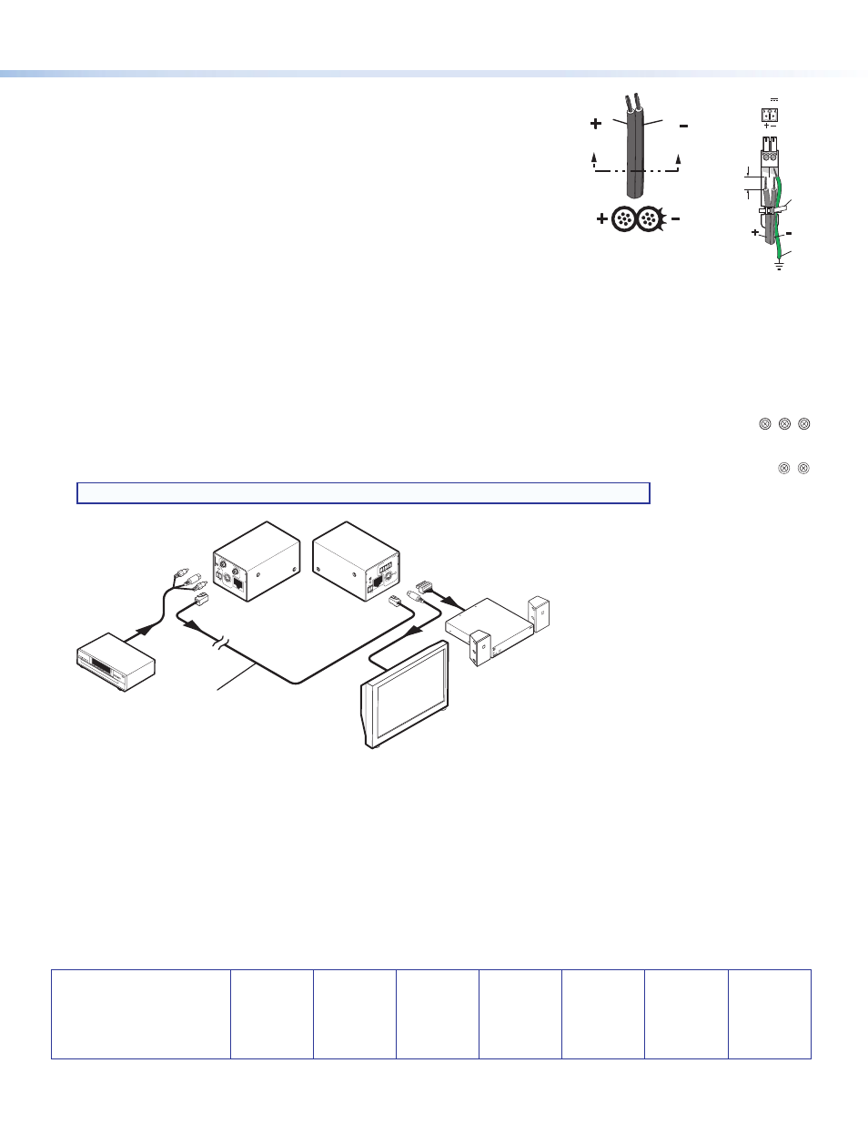
Wire the 2-pole captive screw connectors for the included external 12 VDC power
supplies as shown on the right. Plug one power supply into the transmitter and the
other into the receiver.
Grounding the power input port
Extron MTP AV products can be adversely affected by electrostatic discharge (ESD)
if they are not grounded correctly.
To prevent malfunctions or product damage, an experienced installer can correctly
ground an Extron MTP AV product by inserting one end of the grounding wire to the
negative or ground pin on the power input connector (see the image on the right). Tie
the other end of the wire to an earth ground.
If you have any questions about how to ground a product in a specific application, contact an Extron technical support specialist.
Step 6 — Receiver Sharpness and Gain
z
Sharpness — Adjusts the output image sharpness for long cable runs.
z
Gain control — Adjusts the brightness of the output image to compensate for long cable runs.
z
S-video receivers — There are separate controls for luminance (Y) and chrominance (C).
SHARP
C GAIN
Y GAIN
SHARP
GAIN
S-video Receiver
Composite Video
If the setting is too low, the image may appear in monochrome. Adjust the
chrominance (C gain) until color appears.
z
Composite video receivers — There is only one gain control on composite video MTP
receivers.
NOTE: The control knobs shown above on the right are removable to limit access if desired.
INPUT
MTP T
SV A
RCA
VIDEO
OUTPUT
L
R
12V
0.5a
MAX
OUTPUT
SHARP
L
R
INPUT
VIDEO
12V
0.5a
MAX
MTP R SV A
XP
A 1002
1
2
LIMITER/PR
OTEC
T
SIGNAL
OV
ER
TE
MP
MTP T SV A RCA
Twisted Pair
Transmitter
MTP R SV A
Twisted Pair
Receiver
TP Cable
(up to 1,000')
DVD Player
Flat Panel
Display
Extron
SI 28
Surface-
mount
Speakers
Extron
XPA 1002
Audio Power
Amplifier
Figure 1.
Example of a Typical MTP AV Application