Installation and cabling, Step 1 — mount the switcher, Step 2 — connect mls 608 d inputs – Extron Electronics MLS 608 D Series Setup Guide User Manual
Page 3: Step 3 — connect mls 608 d outputs, Caution
3
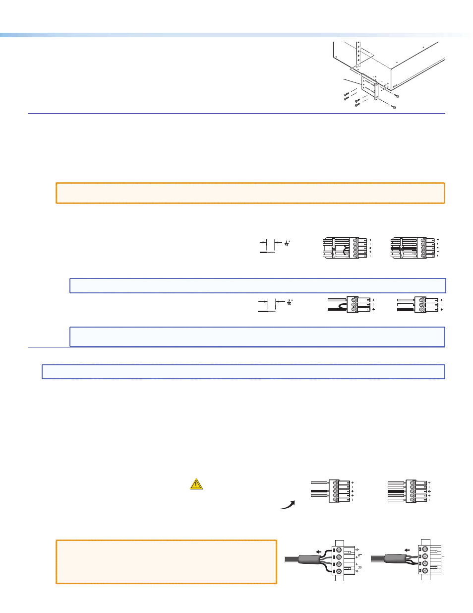
Unbalanced Output
Balanced Output
Tip
NO Ground Here
Sleeve(s)
Tip
NO Ground Here
LR A
UDIO
Tip
Ring
Sleeve(s)
Tip
Ring
LR A
UDIO
CAUTION
For unbalanced audio, connect
the sleeve(s) to the ground contact.
DO NOT
connect the sleeve(s)
to the negative (-) contacts.
Installation and Cabling
Step 1 — Mount the Switcher
Turn off or disconnect all equipment power sources and rack mount
the MLS 608 D using the two supplied brackets (see image at right)
.
Step 2 — Connect MLS 608 D Inputs
Video — Connect inputs from video sources to the applicable connectors marked “Inputs” (see
b
,
d
, and
g
on page 1 for
connector types).
b
Inputs 1-3 — RGB (RGBHV, RGBs, or RGsB), component (bi- or tri-level), S-video, or composite video signals. See rear cover
for connector pin-out table.
d
Input 4 — Universal MTP (video and audio) input on CAT 5, 5e, or 6 twisted pair cabling
CAUTION:
Do not connect the MTP cable to any LAN port, telecommunications network, or digital video output port.
Likewise, do not connect a LAN cable to any MTP, or digital video output port.
g
Inputs 5-8 — Digital HDMI (HDMI 1.3) and DVI-D (using an adapter cable) inputs
Audio — Connect inputs from audio sources to the applicable connectors marked “Inputs”
(see
d
,
i
, and
j
on page 1 for connector types).
i
Inputs 1-3 and 5-8 (line level analog stereo). Wire as shown
at right.
d
I
nput 4 (see
d
above)
.
NOTE:
HDMI inputs 5-8 have the capability to de-embed source input audio (default setting).
j
Mic/line inputs 1-2 (mono). Wire as shown at right.
NOTE:
These inputs have +48 V phantom power available, and the LEDs light when power is present. This power is
turned on or off via software. “Off” is the default setting.
LR
Unbalanced Input
Balanced Input
(high impedance)
(high impedance)
Ring
Sleeve (s)
Tip
Sleeve
Tip
Sleeve
Tip
Tip
Ring
Do not tin
the wires!
(5 mm)
MAX.
2U Rack Mount
Bracket (use four
lower holes)
Balanced Mic Input
Unbalanced Mic Input
Tip
Ring
Sleeve
Tip
Sleeve
(5 mm)
MAX.
Do not tin
the wires!
Step 3 — Connect MLS 608 D Outputs
NOTE:
For TP cables with RJ-45 connectors, use the same standard (T568A or T568B) at both ends
. See rear cover for details.
Video — Connect video output devices to the applicable connectors marked “Outputs” (see
c
,
f
and
h
on page 1
).
c
Buffered output — This signal is always tied to input 1, RGB (RGBHV, or RGBs), component (bi- or tri-level),
S-video, or composite video signals.
f
Analog video output from inputs 1-4, output on CAT 5, 5e, or 6 twisted pair cabling to the MTP/HDMI U R receiver
(see
on page 1)
h
Digital video and RS-232 outputs on CAT 5, 5e, or 6 twisted pair cabling to MTP/HDMI U R receiver (see
on page 1)
Audio — Connect audio output devices to the applicable connectors marked “Outputs” (see f, k and l on page 1)
.
f
MTP analog audio output (line level mono only) on CAT 5, 5e, or 6 twisted pair cabling
k
Two line level audio outputs.
Wire as shown at right
.
l
Power amplifier output, either as
2-channel stereo, 20 watts per channel (MLS 608 D SA model) or mono audio, 40 watts per channel,
70 volts (MLS 608 D MA model). Wire as shown at below right
.
CAUTIONS:
• Do not connect L and R output channels to each other,
or to ground. Doing so will short the outputs and
damage the amplifier.
• Do not short the “ +” and “_” connectors together.
Doing so will damage the amplifier.
NC
NC
To 70 V Speaker
5 mm Captive Screw
MLS 608 D MA Wiring
L
R
To 4/8 Ohm
Speaker Load
5 mm Captive Screw
MLS 608 D SA Wiring