Mmx 32 vga mtp • setup guide (continued), Front panel operation, Device control – Extron Electronics MMX 32 VGA MTP Setup Guide User Manual
Page 2
MMX 32 VGA MTP • Setup Guide (Continued)
SECTION A–A
A
A
Power Supply
Output Cord
2-Pole Captive Screw
Connector
Ridges
Smooth
Tie Wrap
3/16”
(5 mm) Max.
SYNC -
TRI
PRE PEAK - ON
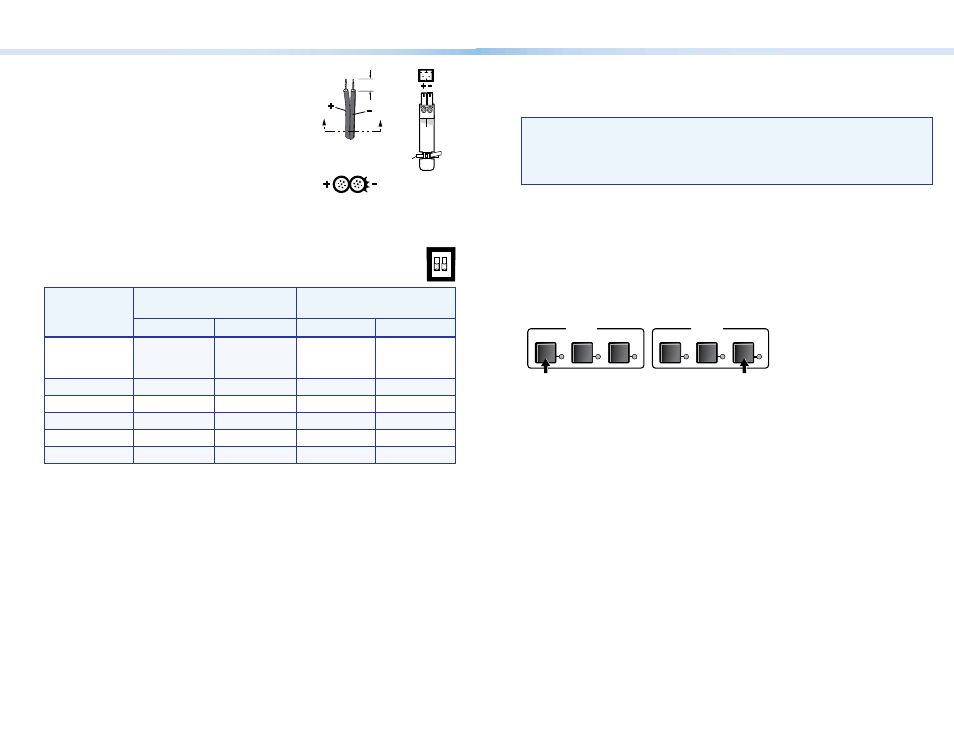
Step 5 — Power
Plug the included external 12 VDC power supply into the
2-pole captive screw connector. Wire the connector as
shown at right.
Step 6 — Pre-Peaking and Sync Selection
Pre-Peaking — To compensate for signal loss over long cable runs, set the DIP switch
position (up = on, down = off) as shown in the table below:
Video Format
Cable length
Signal quality at max.
distance
Pre-Peak Off
Pre-Peak On
High
Variable
Composite,
S-video,
Component
800 ft
(245 m)
1000 ft
(300 m)
640 x 480
<300 ft (90 m)
>350 ft (105 m)
700 ft (215 m)
750 ft (230 m)
800 x 600
<300 ft (90 m)
>350 ft (105 m)
550 ft (165 m)
650 ft (200 m)
1024 x 760
<300 ft (90 m)
>350 ft (105 m)
500 ft (150 m)
600 ft (185 m)
1280 x 1024
<250 ft (75 m)
>300 ft (90 m)
350 ft (105 m)
450 ft (135 m)
1600 x 1200
<250 ft (75 m)
>300 ft (90 m)
300 ft (90 m)
450 ft (135 m)
Sync selection — To select either bi-level sync or tri-level sync on output 2, set the sync DIP
switch to the desired setting (up = tri-level sync, down = bi-level sync).
Front Panel Operation
Outputs 1 and 2 — For each output press the button for the desired input (1, 2 or 3). The
LED for that input lights.
NOTE:
When power is applied, the LEDs light sequentially from left to right. For first
time power up, the default configuration is input 1 tied to both outputs
1 and 2, the front panel is not locked, and all states are unmuted. Input 1 LEDs
for output 1 and for output 2 are both lit. If this is not a first time power up,
then the LEDs for the last valid input selections light.
Front Panel Security Lock Out (Executive Mode)
Locking the front panel protects the switcher from unwanted tampering. While the
switcher is locked, the user can select inputs only through a remote device.
To lock or unlock the front panel, press the following buttons simultaneously and hold
them for at least 3 seconds:
• For output 1 press and hold input 1 button.
• For output 2 press and hold input 3 button.
The front panel LEDs flash to indicate the front panel is locked.
OUTPUT 1
2
1
3
OUTPUT 2
2
1
3
Press and hold Input 1
Button for Output 1.
Press and hold Input 3
Button for Output 2.
System Reset
To reset the switcher to its factory settings, press and hold the input 3 button
for output 1 while powering up the switcher.
Audio Switching
When you select an input, the audio and video signals from that input are
routed together to the appropriate output.
Audio breakaway is possible through the Extron Simple Instruction Set (SIS)
or the Extron Universal Switcher Control Program. When audio breakaway is
active, the front panel input LED for the audio source flashes, while the LED of
the video source lights steadily.
Device Control
Output Control
Momentarily short the rear panel Remote contact pin 1, 2, or 3 for the desired output to
ground to switch to that input.
Use the +5 V port when controlling the output with an MMX 32 AAP or MMX 32 MAAP
panel.
RS-232 Control
Software control via the RS-232 connection is possible using the Extron Simple Instruction
Set (SIS) or the Extron Windows
®
-based control program. The RS-232 connector on the
MMX 32 VGA MTP is a 3-pole captive screw connector.