Extron Electronics IN3218 User Manual
Page 11
7
© 1997 - INLINE, INC.
IN3212 / IN3214 / IN3218 OPERATION MANUAL - REV. 1 10/25/97
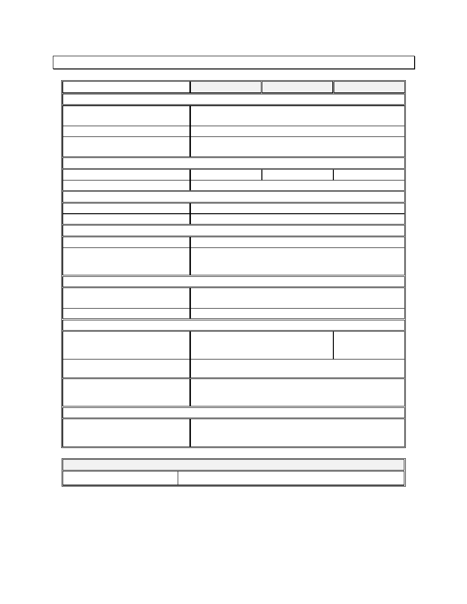
SPECIFICATIONS
IN3212
IN3214
IN3218
Inputs
Input 1
(1) BNC for composite video signals
Termination: 75O or High Z
Signal
Analog Video, 1.5 Vp-p max.
Loop Out / Input 2
(1) BNC
Termination: 75O or High Z
Output
Connectors
2 BNC female
4 BNC female
8 BNC female
Impedance
75O
Controls
Gain Range
0.7 (30% decrease) to 1.4 (40% increase)
Peaking
Optimized for NTSC/PAL/SECAM Signals
General
Bandwidth
300 MHz @ -3dB
Internal Jumpers
(2) Input Termination
(2) Normal / Split Mode
(4) AC/DC Coupling (IN3218 only)
Power
Voltage
9 VDC
500 mA external adapter included
Power Consumption
Dimensions
Height x Width x Depth
4” x 5.6” x 1.25” /
10.2cm x 14.2cm x 3.2cm
4” x 5” x 1.6” /
10.2cm x 12.7cm x
4cm
Weight
Product weight: 0.75 lbs. / 0.35 Kg
Shipping weight: 2 lbs. / 1Kg
Regulatory Approvals
UL1950, CAN/CSA-22.2 No.950, Third Edition
CE: EN5502 (1987), EN50081-1 (1991),
EN50082-1 (1992 and 1994), EN0950-92
Parts Included
IN9204 9 VDC 500 mA Power Supply
IN9333 Gain / Peaking Adjustment Tool
Operation Manual
Optional Accessories
Mounting Brackets
IN9127 (for IN3214/IN3218); IN9128 (for IN3218).