Setup guide — in3252hr (cont’d), Step 6 — adjust video gain and peaking, Step 7 — mount the da – Extron Electronics IN3252HR Setup Guide User Manual
Page 2
Setup Guide — IN3252HR (cont’d)
Step 5 — Power on DA, input/output
devices, and check for picture
Plug the external power supply cord into the DA
(
a
) and turn on the input and output devices.
The picture should appear. If not, ensure that
all devices are plugged in and receiving power.
Check cabling and make adjustments as needed.
N
The BNCs for the output(s) and input
must be connected with an identical signal.
C Always use a power supply supplied or
specified by Extron. Use of an
unauthorized power supply voids all
regulatory compliance certification and
may cause damage to the supply and the
end product. Unless otherwise stated,
the AC/DC adapters are not suitable
for use in air handling spaces or in wall
cavities. The installation must always
be in accordance with the applicable
provisions of National Electrical Code
ANSI/NFPA 70, article 75 and the
Canadian Electrical Code part 1,
section 16. The power supply shall
not be permanently fixed to building
structure or similar structure.
Step 6 — Adjust video gain and peaking
With an oscilloscope:
a.
Feed a grayscale signal from an Extron VTG 300/400 to the input of the IN3252HR.
b.
Remove the green output cable attached to the display device and connect it to the
oscilloscope with 75 ohm termination.
c.
Adjust the green gain control (
d
) to achieve 0.7 Vp-p for the white bar of the test pattern.
d.
Repeat steps b and c for the red and blue channels.
e.
Adjust the peaking by connecting the green output cable from the display device to
the oscilloscope and adjusting the peaking control (
e
) until no overshooting or round
corners appear on the test pattern.
f.
Plug the red, green, and blue cables back into the display device.
Without an oscilloscope:
a.
Feed a grayscale signal from an Extron VTG 300/400 to the input of the IN3252HR.
b.
Adjust the green gain control (
d
) until the picture from the display device appears to
have the correct brightness and contrast.
c.
Adjust the red and blue controls (
d
) until the grayscale picture appears to be gray only.
No color should be present.
d.
Adjust the peaking control (
e
) until the picture appears sharp with no visible smearing.
Step 7 — Mount the DA
If necessary, mount the DA. For mounting information, see the IN3252HR User’s Guide or
refer to the bottom of the DA.
68-824-50
Rev. B
03 10
RGBHV DISTRIBUTION AMPLIFIER
IN3252HR
3
1
4
2
2
3
5
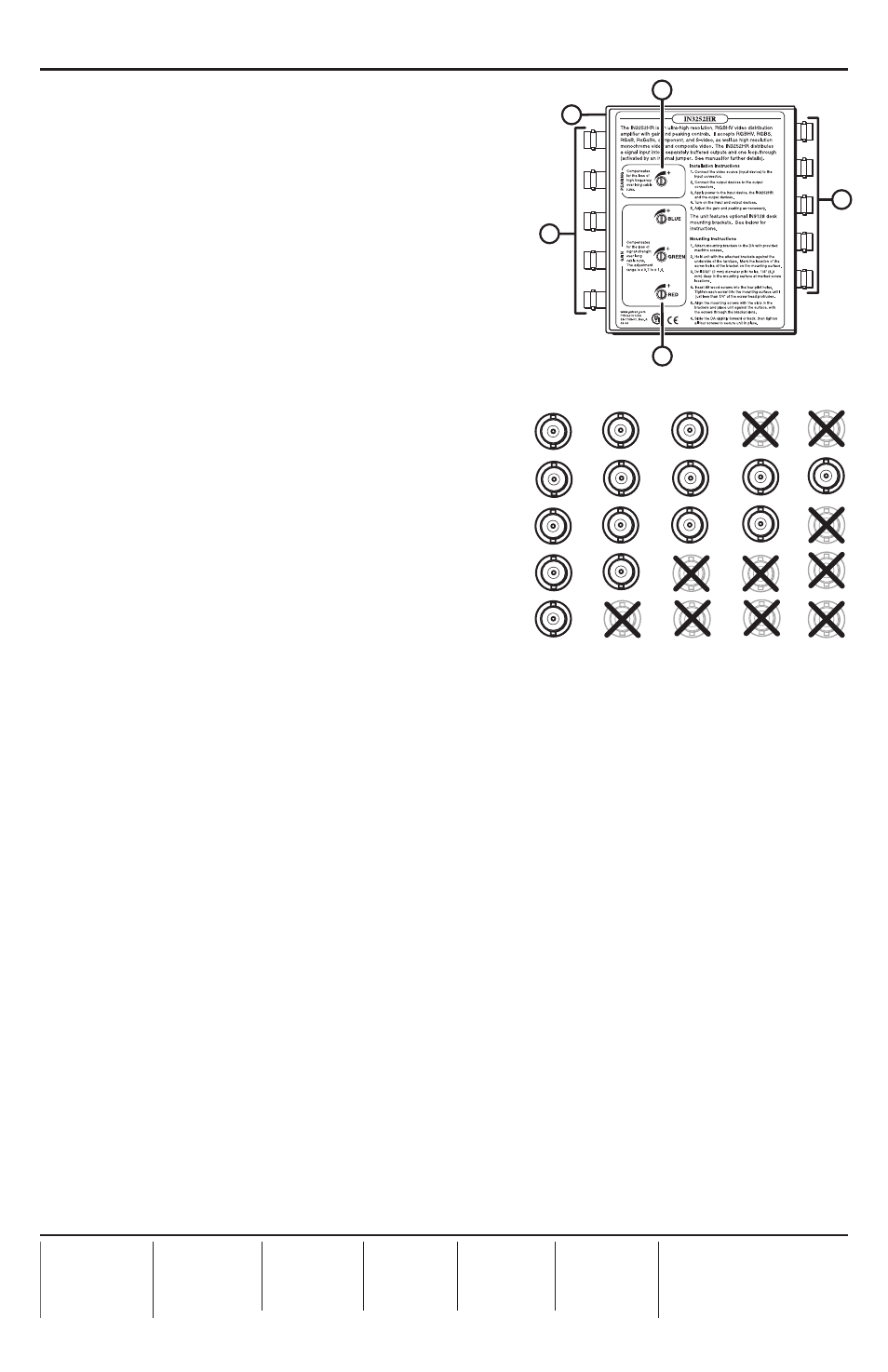
Bottom view
Peaking
control
Power
connector
Outputs
Input
Gain
controls
R
G
B
H
V
RGBHV
RGBS
RGsB,
RsGsBs,
Component
S-video
Composite
video
Figure 3 – Connectors/controls and
BNC connection diagram