Extron Electronics IN1606 Setup Guide User Manual
In1606 • setup guide, Installation, Rear panel features
1
IMP
ORT
ANT
:
Go to www
.extr
on.com f
or the
complete user guide
, installation
instructions,
and specifications.
IN1606 • Setup Guide
The Extron IN1606 Scaling Presentation Switcher is a six input, HDCP-compliant video scaler that accepts a wide variety of audio and video
formats. This guide allows an experienced user to set up and configure the IN1606. It covers how to perform basic operations using the front panel
controls and selected Simple Instruction Set (SIS™) commands.
NOTE:
For full installation, configuration, menus, connector wiring, and operation details, see the IN1606 and IN1608 Series User Guide, at
Installation
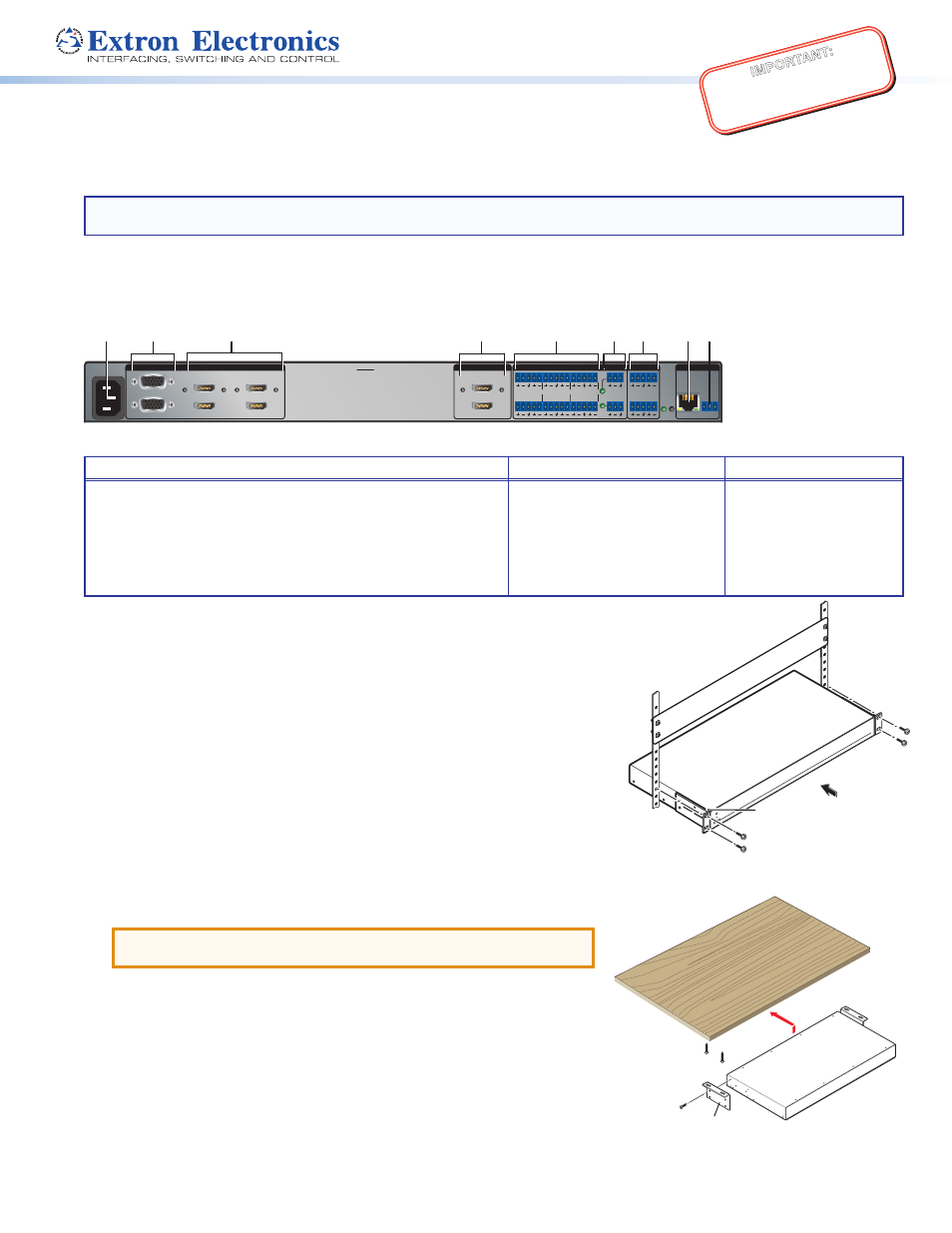
Rear Panel Features
100-240V ~ 50/60 Hz
0.5 A MAX
1
2
CONFIGURABLE
HDMI
IN1606
HDMI
5
6
HDMI
A
B
3
4
INPUTS
OUTPUTS
AUDIO INPUTS
OUTPUTS
REMOTE
L
1
R
L
2
R
L
3
R
L
4
R
L
5
R
+48V
+48V
1
2
L
R
VARIABLE
Tx Rx
RS-232
G
LAN
RESET
1
2
MIC/LINE
L
6
R
a
b
c
f
d
e g
h i
Figure 1.
Rear Panel Connectors
Power and Input Connections
Output Connections
Control Connections
a
AC power connector
b
Configurable analog 15-pin HD (VGA) connectors (inputs 1 and 2)
c
HDMI input connectors (inputs 3 through 6)
d
Analog audio input connectors (associated with inputs 1 through 6)
e
Mic/Line audio input connectors and adjacent phantom power LEDs
f
HDMI output connectors
g
Analog audio output connectors
h
LAN connector
i
RS-232 connector
Mounting and Cabling
Step 1 — Mounting
a.
Turn off or disconnect all equipment power sources.
b.
Mount the IN1606 to a rack using the pre-installed rack ears (see figure 2) or remove the
rack ears and use an optional mounting kit for under-the-desk mounting (see figure 3).
Step 2 — Connecting inputs
a.
Connect analog video sources to the 15-pin HD connectors (see
b
above).
b.
Connect digital HDMI or DVI (with an appropriate adapter) sources to the HDMI
connectors (see
c
above).
c.
Connect audio input sources to the 5-pole captive screw connectors (see
d
above).
d.
Connect Mic/Line input sources to the 3-pole captive screw connectors (see
e
above).
Step 3 — Connecting outputs
a.
Connect suitable video displays to the HDMI connectors (see
f
above).
b.
Connect audio output devices to the 5-pole captive screw connectors (see
g
above).
ATTENTION:
For unbalanced outputs, do not connect wires to the “-” poles
(see the IN1606 and IN1608 Series User Guide for wiring details).
Step 4 — Connecting control devices
a.
For control through Ethernet, connect a LAN or WAN to the RJ-45 connector
(see
h
above). The default IP address is 192.168.254.254. The default subnet mask is
255.255.0.0.
b.
For serial RS-232 control, connect a host device to the 3-pole captive screw connector
(see
i
above). The default baud rate is 9600.
c.
For control through USB, connect a host device to the front panel mini USB B port.
(see
a
on page 2).
Step 5 — Connecting power
Connect a 100 to 240 VAC, 50-60 Hz power source to the power AC power connector (see
a
above).
Figure 2.
Rack Mount
Figure 3.
Furniture Mount
Rack Ears
#8 Screw
(4) Places
Each Side
MBU 149
Mounting Bracket
Mounting Screws
(2) Places
Each Side