Set each receiver to daisy chain mode. see, Return link, And daisy chain modes – Extron Electronics FOXBOX SR HDMI Setup Guide User Manual
Page 2: Foxbox sr hdmi • setup guide (continued), Operation, Return link and daisy chain modes, Hdmi audio switch, Indications, Setup
2
c.
If you want the receiver to pass serial data or control signals, such as for serial control of a
ALARM
Tx Rx
1 2
RS-232
OVER FIBER
projector, connect the master device to the transmitter and the slave device to the receiver via the left three poles
(Tx, Rx, and
_
) of the RS-232 Over Fiber/Alarm 5-pole captive screw connectors on both units.
d.
For serial control of a unit, connect a host device, such as a computer, to one of the following ports on the unit to be
controlled:
Transmitter or receiver Configuration port — A 2.5 mm mini jack. A TRS RS-232 cable is included with the transmitter.
CONFIG
Receiver Remote RS-232 port — Use the Remote RS-232 3-pole captive screw connector.
The protocol for both of these ports is as follows:
REMOTE
RS-232
Tx Rx
•
RS-232
•
9600 baud
•
no parity
•
8 data bits
•
1 stop bit
•
no flow control
e.
For remote monitoring of the status of the Rx optical link on either the transmitter or receiver, connect a locally
ALARM
Tx Rx
1 2
RS-232
OVER FIBER
constructed or obtained device to the two right Alarm poles of the RS-232 Over Fiber/Alarm 5-pole captive screw
connector on that unit. The unit shorts both poles together when no light is detected.
Operation
After all receivers, the transmitter, and their connected devices are powered up, the system is fully operational. If any problems are
encountered, verify that the cables are routed and connected properly and that all display devices have identical resolutions and
refresh rates. If problems persist, call the Extron S3 Sales and Technical Support Hotline at the number that is closest to you.
Return Link and Daisy Chain Modes
The receiver operates in one of two modes (or both modes can be disabled):
Return link mode — The receiver outputs data on its Tx connector for return to the transmitter.
Daisy chain mode — The receiver daisy-chains its Rx connector input through to its Tx connector output.
Issue the following SIS commands from a PC connected to the receiver Remote RS-232 port to toggle between return link and daisy
chain modes or to disable both modes:
66*0*n#, where n =
0
= disable,
1
= enable return link (default mode), and
2
= daisy chain enable
NOTES:
•
Up to 10 receivers, each in daisy chain mode, can be connected in a daisy chain to a single transmitter.
•
Daisy chain mode works with non-HDCP sources only.
HDMI Audio Switch
HDMI AUDIO
OFF
ON
This switch mutes (Off position) and unmutes (On position) the embedded audio output on the HDMI output connector.
The audio on the captive screw output always remains active regardless of the setting of this switch.
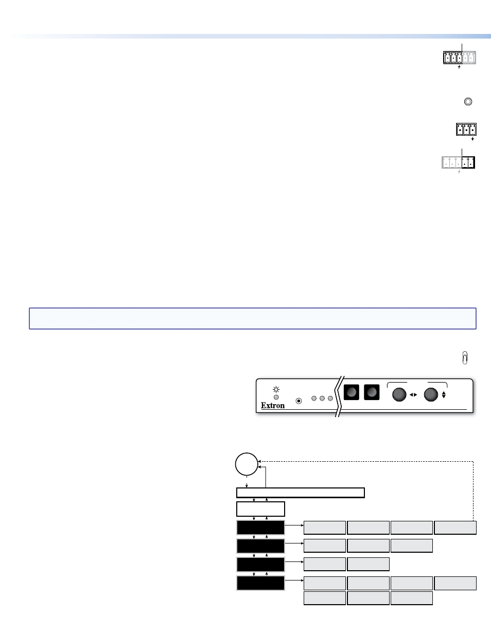
Indications
FOXBOX SR HDMI
AUDIO
HDCP
VIDEO
CONFIG
MENU
ENTER
ADJUST
Power LED — This LED lights to indicate that power is applied to
the unit.
Video LED — This LED lights when the receiver detects a signal
on its video input.
HDCP LED — This LED lights when the video signal is HDCP encrypted.
Audio LED — This LED lights when the receiver detects a low level audio signal for a short period of time.
Setup
Menu
No
menu
display
Menu
Timeout
AUTO
IMAGE
EXTRON ELECTRONICS FOXBOX SR HDMI
Enter
PICTURE
CONTROLS
Enter
OUTPUT
CONFIGURATION
Enter
USER
PRESETS
Enter
ADVANCED
CONFIGURATION
H POSITION V
+0 +0
BRIGHT CONT
64 64
H SIZE V
1024 768
RESOLUTION
1024X768 @60
HDMI FORMAT
AUTO
RECALL
2
SAVE
<2>
CLEAR
<2>
DETAIL
0
TEST PATTERN
CROP
FREEZE
OFF
ASPECT
RATIO
BLANK
OFF
AUTO MEMORY
ON
FACTORY RESET
HOLD ENTER
MENU TIMEOUT
10
Use the front panel menu controls and the on-screen
display, shown at right, on the connected display to set up
the receiver.
68-1990-50
Rev A 08 12
© 2012 Extron Electronics. All rights reserved.
www.extron.com
FOXBOX SR HDMI • Setup Guide (Continued)