Power supply connection, Video output connections, Audio output connections – Extron Electronics Fox Tx_Rx AV Setup Guide User Manual
Page 2: Fiber optic cable connections, Extron contact information, Fox tx/rx av • setup guide (continued), Step 7, Step 8, Step 9, Step 10
2
Fox Tx/Rx AV • Setup Guide (Continued)
Extron USA - West
Headquarters
+800.633.9876
Inside USA/Canada
Only
+1.714.491.1500
+1.714.491.1517 FAX
Extron USA - East
+800.633.9876
Inside USA/Canada
Only
+1.919.863.1794
+1.919.863.1797 FAX
Extron Europe
+800.3987.6673
Inside Europe Only
+31.33.453.4040
+31.33.453.4050 FAX
Extron Asia
+800.7339.8766
Inside Asia Only
+65.6383.4400
+65.6383.4664 FAX
Extron Japan
+81.3.3511.7655
+81.3.3511.7656 FAX
Extron China
+400.883.1568
Inside China Only
+86.21.3760.1568
+86.21.3760.1566 FAX
Extron Middle East
+971.4.2991800
+971.4.2991880 FAX
Step 7
Connect the 12 VDC power supply to the 2-pole captive screw connector on the transmitter. Do not switch on the power
supply.
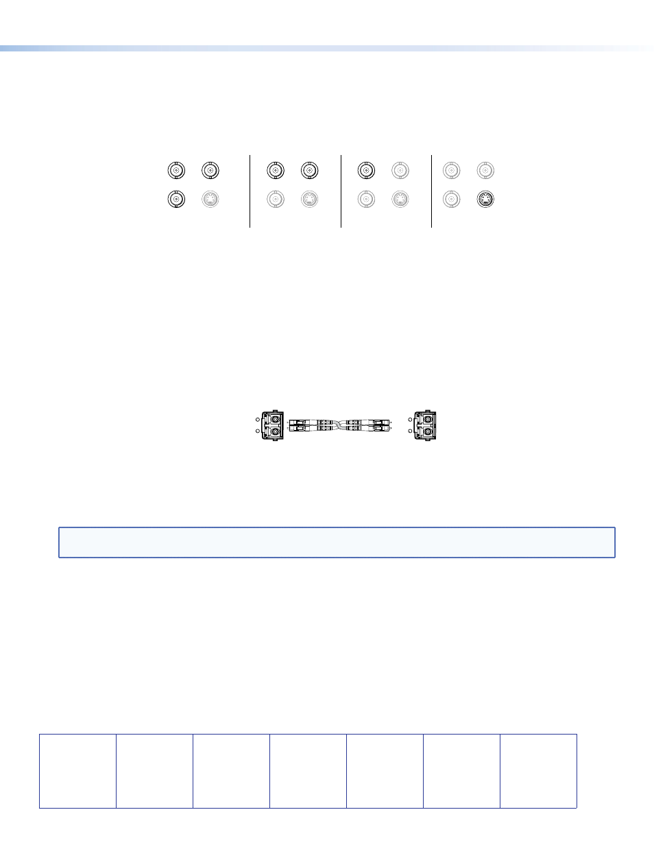
Step 8
Connect the receiver to a low resolution video display using either the output BNC connectors (component, S-video, or
composite) or the 4-pin mini DIN (S-video only), as shown in the figure below.
Y/VID
R-Y
S-VID
B-Y/C
Y/VID
S-video (DIN)
R-Y
B-Y/C
Y/VID
R-Y
S-VID
B-Y/C
S-VID
S-video (BNC)
R-Y
Y/VID
R-Y
S-VID
B-Y/C
S-VID
Component
Y/VID
R-Y
S-VID
B-Y/C
S-VID
Composite
R-Y
B-Y/C
Step 9
Connect the audio output from the receiver to a sound system, using the 5 pole, 3.5 mm captive screw connector.
Step 10
If required, connect an alarm system to the 2-pole captive screw connector (marked Alarm) on the receiver.
Step 11
Connect the fiber optic cable(s) from the transmitter to the back of the receiver (see the figure below). Fiber optic link 1
connects the Tx port of the transmitter to the Rx port of the receiver and is essential for transmission of video, audio, and
control signals from the transmitter to the receiver. Fiber optic link 2 connects the Rx port of the transmitter to the Tx
port of the receiver. Although it is optional, two-way communication from the Tx port of the receiver is required to fully
configure the system using RS-232 commands or FOX Extender Windows Control Program.
Rx
Tx
OPTICA
L
Rx
Tx
OPTICA
L
Transmitter
Receiver
Link 2 may be connected to another receiver in a daisy chain. In that case, there is no return link to the transmitter.
Step 12
Connect an RS-232 control device to the 5-pole captive screw connector or the front panel Config port of the receiver. These
ports are an alternative to the transmitter ports (see steps 5 and 6).
NOTE:
If the RS-232 control device is connected to the receiver, fiber optic link 2 is required to configure the transmitter.
Step 13
Connect the 12 VDC power supply to the 2-pole captive screw connector of the receiver.
Step 14
Power up all devices and configure the system using the Simple Instruction Set (SIS™) commands or FOX Extender Windows
Control Program. Consult the user guide (available online at www.extron.com) for more information about SIS commands
and the Control Program.
68-1466-50
Rev B
11 10