Fox t usw 203 • installation guide (continued), Operation, Input selection buttons – Extron Electronics FOX T USW 203 Installation User Manual
Page 2: Remote control, Indicators, Input selection, Front panel lockout mode (executive mode), Auto switch mode, Normal switch mode, Step 2 - making connections
2
FOX T USW 203 • Installation Guide (Continued)
68-2226-50
Rev. A
07 13
Extron Headquarters
+1.800.633.9876 (Inside USA/Canada Only)
Extron Asia
+65.6383.4400
Extron China
+86.21.3760.1568)
Extron Korea
+82.2.3444.1571
Extron Europe
+31.33.453.4040
Extron Japan
+81.3.3511.7655
Extron Middle East
+971.4.299.1800
Extron India
+91.80.3055.3777
© 2013 Extron Electronics — All rights reserved. All trademarks mentioned are the property of their respective owners.
www.extron.com
h
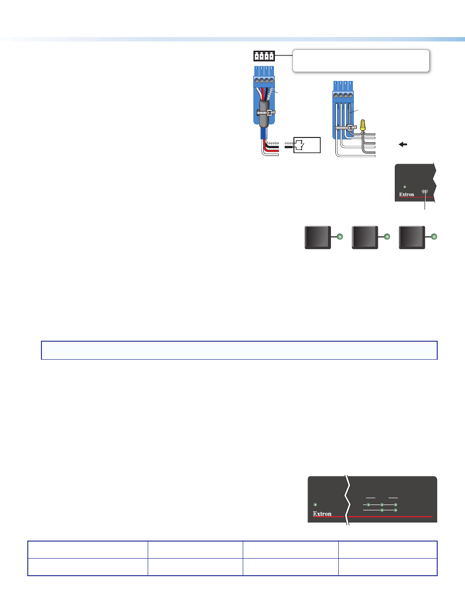
Remote contact closure connector — Connect a suitable contact
closure device to this 3.5 mm, 4-pole captive screw connector for
remote input selection.
i
Remote RS-232 connector — For serial RS-232 control of the FOX
T USW 203 and firmware upgrades, connect a host device or control
system to this 3.5 mm, 3-pole captive screw connector (see
below).
j
Power connector — Connect the provided 12 VDC external power
supply to this 2-pole captive screw connector.
k
Config port — Connect a host device, such as a computer, to the front panel mini Type B USB connector to provide
configuration, control, or firmware upgrades to the switcher (see
below).
Operation
Input Selection Buttons
The three buttons with corresponding LEDs on the front panel (labeled Mode or 1, Normal or
2, and Auto or 3) manually select inputs 1 through 3 and enable different operating modes. The
LEDs light to indicate the active input and provide feedback.
Input selection
Press the input selection button that corresponds with desired rear panel input connector to
activate that input signal.
Front panel lockout mode (executive mode)
Push and hold input buttons 1, 2, and 3 simultaneously for 5 seconds to enable or disable front panel configuration. All of the front panel LEDs
blink 3 times. In executive mode, contact closure and RS-232 control are still available.
Auto switch mode
Press and hold input buttons 1 and 3 simultaneously for 3 seconds. After releasing the buttons, the Auto Switch LED lights to indicate that auto
switch mode is enabled. This prioritizes the highest numbered active input.
NOTE:
Setting auto switch mode to prioritize the lowest numbered active input can be done only with SIS commands (see the
FOX T USW 203 User Guide for more details).
Normal switch mode
Press and hold inputs 1 and 2 simultaneously for 3 seconds. After releasing the buttons, the Auto Switch LED turns off to indicate that auto switch
mode is disabled. This is the default mode.
Remote Control
The FOX T USW 203 can be controlled through the Extron FOX Extenders Control Software, SIS commands, remote RS-232, or a contact closure
device (see
for connection details).
Install the FOX Extenders Control Software on a computer running a Windows
®
operating system. The control program can be installed from the
Extron Software Products DVD or downloaded from the Extron website,
(see the
FOX T USW 203 User Guide).
Indicators
Auto Switch LED — Lights when the device is in auto switch mode.
Input selection LEDs — Light to signify status or give feedback of the currently selected input
(see
above).
Signal Status LEDs — Light when an input signal is detected on the corresponding input.
HDCP status LEDs — Light when an HDMI input signal is HDCP compliant. Input 1 has no
HDCP capabilities.
1
2
3
MODE
NORMAL
AUTO
FOX T USW 203
AUTO
SWITCH
MODE
CONFIG
NORMAL
1
2
AUTO
SIGNAL
HDCP
STATUS
3
1
2
3
k
FOX T USW 203
FOX UNIVERSAL SWITCHER
SIGNAL
HDCP
STATUS
1
2
3
AUTO
SWITCH
CONTACT
1 2 3 G
Ground
Wire Nut
Device 3
Device 2
Device 1
Remote Contact Closure
Each port senses an external switch or contact closure.
Use these ports to select an input on the switcher.
(Switches,
relays, or
similar items)
Switch
1
2
3
G
Heat
Shrink
Over
Shield
Wires