Extron Electronics FOX SW8 Setup Guide User Manual
Fox sw8 • setup guide, Installation, Step 1 — mounting
FOX SW8 • Setup Guide
This guide provides quick start instructions for an experienced installer to set up and operate the
Extron FOX SW8 fiber optic switcher.
WARNING:
Vision hazard — This unit outputs continuous laser light, which may be harmful
to the eyes; use with caution. For additional safety, plug the attached dust caps into the
optical transceivers when the fiber optic cable is unplugged.
CLASS 1 LASER PRODUCT, see the FOX SW8 User Guide, available at
www.extron.com
.
4
5
6
7
8
FOX SW8
100-240V 0.3A
OPTICAL INPUTS
50/60 Hz
RS-232
Tx
Rx
OUTPUT
LOOP IN
1
LOOP IN
2
LOOP IN
LOOP IN
LOOP IN
LOOP IN
LOOP IN
OUT IN
3
FOX 500 Tx
100-240V 0.3A
50/60 Hz
AUDIO INPUTS
INPUT LOOP THRU
RGB INPU
T
R
G
B
H
V
OR
L
R
RS-232
PASS THRU
Tx
Rx
NA
RS-232
CO
NT
RO
L
ALARM
* OPTIONAL FOR
RE
TUR
N D
ATA
LINK
LINK
Tx
Rx
1
2
RG
B
OPTICA
L
1
2*
FOX 500 Tx
100-240V 0.3A
50/60 Hz
AUDIO INPUTS
INPUT LOOP THRU
RGB INPU
T
R
G
B
H
V
OR
L
R
RS-232
PASS THRU
Tx
Rx
NA
RS-232
CO
NT
RO
L
ALARM
* OPTIONAL FOR
RE
TUR
N D
ATA
LINK
LINK
Tx
Rx
1
2
RGB
OPTICA
L
1
2*
POWER
12V
3A
MA
X
OUTPUT
4/8
OHMS
INPUTS
L
R
L
R
REMOTE
VOL/MU
TE
10V
50m
A
L
MP
A 15
2
R
C
US
LIST
ED
17T
T
AU
DIO
/VI
DE
O
AP
PA
RA
TU
S
CLASS 2 WIRING
DO NOT GROUND
OR SHOR
T
SPEAKER OUTPUTS!
Extron
FOX 500 DVI
Fiber Optic Receiver
Flat Panel
Display
DVI Output
Audio Output
RGB Input
Extron
FOX 500 Tx
Fiber Optic
Transmitter
Extron
FOX SW8
Fiber Optic Switcher
Audio Input
PC
Local
Monitor
RGB Input
Extron
FOX 500 Tx
Fiber Optic
Transmitter
8 Inputs
Audio Input
PC
Local
Monitor
Extron
MPA 152
Mini Power
Amplifier
Extron
SI 26X
Two-way Ceiling
Speakers
Installation
100-240V 0.3A
50/60 Hz
RS-232
Tx Rx
FOX SW8
OPTICAL INPUTS
LOOP IN
LOOP IN
LOOP IN
LOOP IN
LOOP IN
LOOP IN
LOOP IN
OUT IN
1
2
3
4
5
6
7
8
6
3
4
5
2
3
3
2
3
3
2
3
3
2
2
2
2
2
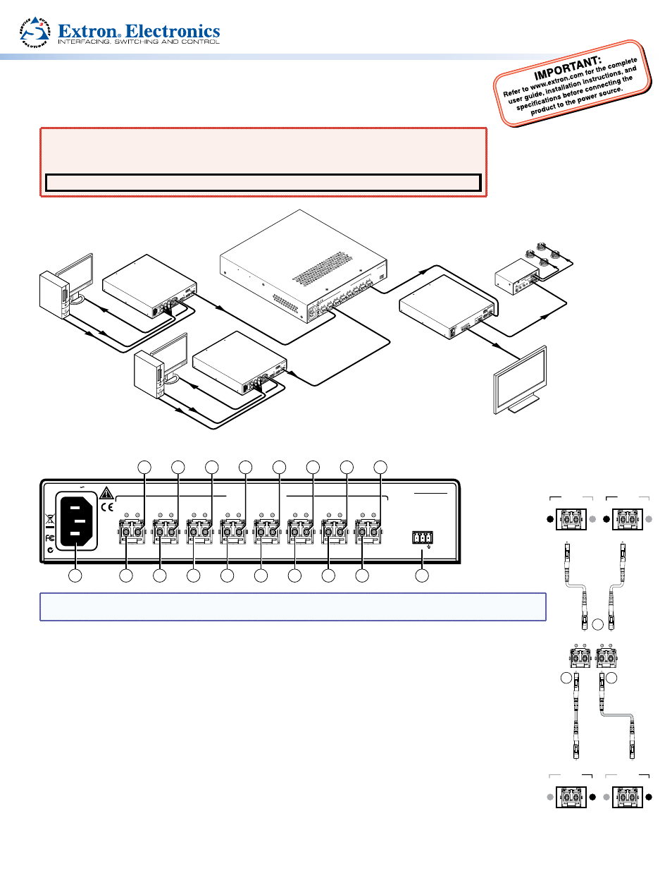
NOTE: Steps 2 through 4 are for an 8-input, 1-output switcher in a system that is not HDMI compliant.
For HDCP compliance, the unit can be configured as 7-input, 1-output only. See the
NOTE after step 4.
Step 1 — Mounting
Turn off or disconnect all equipment power sources and mount the FOX switcher as required.
Step 2 — Optical Inputs
Connect up to eight fiber optic transmitters to rear panel Input LC connectors of the FOX switcher
(the right-hand connector on each transceiver block).
Step 3 — Loop Optical Outputs
Connect up to seven fiber cables between the Loop LC connectors of the FOX switcher (the left-hand connector
on transceiver blocks 1 through 7) and compatible receivers for unswitched outputs (each input loops through to
its associated output only).
OPTICAL
1
2*
*
OPTIONAL FOR
RETURN DATA
LINK
LINK
Transmitter
#7
Receivers
OPTICAL
1
2*
*
OPTIONAL FOR
RETURN DATA
LINK
LINK
Transmitter
#8
Loop (Local)
Application
Switcher
OPTICAL
2*
1
LINK
LINK
2
3
LOOP IN
OUT IN
7
8
Switched
Application
OPTICAL
2*
1
LINK
LINK
4
8-input, Non-HDCP
Configuration