Indication and control, Operation, Embedded web pages – Extron Electronics FOX RS 104 Setup Guide User Manual
Page 2
2
68-2172-50
Rev. A 02 13
Extron Headquarters
+800.633.9876 Inside USA/Canada Only
Extron USA - West
Extron USA - East
+1.714.491.1500 +1.919.850.1000
+1.714.491.1517 FAX
+1.919.850.1001 FAX
Extron Europe
+800.3987.6673
Inside Europe Only
+31.33.453.4040
+31.33.453.4050 FAX
Extron Asia
+800.7339.8766
Inside Asia Only
+65.6383.4400
+65.6383.4664 FAX
Extron Japan
+81.3.3511.7655
+81.3.3511.7656 FAX
Extron China
+4000.EXTRON
+4000.398766
Inside China Only
+86.21.3760.1568
+86.21.3760.1566 FAX
Extron Middle East
+971.4.299.1800
+971.4.299.1880 FAX
Extron Korea
+82.2.3444.1571
+82.2.3444.1575 FAX
Extron India
1800.3070.3777
Inside India Only
+91.80.3055.3777
+91.80.3055.3737
FAX
©
2013 Extron Electronics All rights reserved. All trademarks mentioned are the property of their respective owners.
www.extron.com
ü
Rx B — For one-way transmission from an upstream device, which typically can be either a transmitter or a receiver,
depending on the application, connect a fiber optic cable to the Rx B LC connector. Connect the free end of this fiber
optic cable to the Tx connector on the upstream device.
Tx Link and Rx Link LEDs — When lit, the link is active (light is received).
b
LAN port — For IP control of the inserter with SIS commands or downloaded HTML pages from the inserter and to insert
serial data into and extract it from the fiber stream, connect the unit to a PC or to an Ethernet LAN via this RJ-45 connector.
You can use a PC for control and serial data insertion and extraction from anywhere in the world.
Link LED indicator — The green (link) LED indicates that the inserter is properly connected to an Ethernet LAN. This LED
should light steadily.
Act LED indicator — The yellow (activity) LED indicates transmission of data packets on the RJ-45 connector. This LED
should flicker as the inserter communicates.
c
AC power connector — Plug a standard IEC power cord into this connector to connect the FOX RS 104 to a
100 VAC to 240 VAC, 50-60 Hz power source.
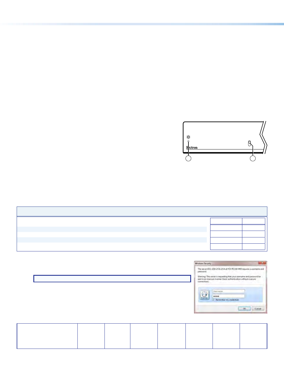
Indication and Control
4.25G
2.125G
INPUT DATA RATE
Front
4
5
d
Power LED — This LED lights green when power is applied.
e
Input Data Rate switch — This switch selects between the 2.125 Gbits (2G)
and 4.25 Gbits (4G) input data rate. After switching data rates, cycle inserter
power to properly lock onto the selected input data rate.
Operation
To insert RS-232 commands into or extract RS-232 responses from the fiber optic signal stream, you need to connect a computer
or other Ethernet-capable device to the rear panel LAN port and operate the inserter using either SIS commands or the built-in
HTML pages.
Selected SIS Commands — Enable and Disable Serial Insertion Ports
Command
ASCII Command
(host to unit)
Response
(unit to host)
Additional description
Enable one port
EX!
*1LRPT
}
Lrpt
X!
*1
]
Enable serial insertion port
X!
(allow data to
be inserted onto fiber optic port
X!
).
X!
=
UART Port
Telnet port
1
2001
2
2002
3
2003
4
2004
Disable one port
EX!
*0LRPT
}
Lrpt
X!
*0
]
Disable serial insertion port
X!
.
Enable all ports
E
0*1LRPT
}
Lrpt0*1
]
Disable all ports
E
0*0LRPT
}
Lrpt0*0
]
View port status
EX!
LRPT
}
X@]
X@
=
0 (disabled) or 1 (enabled).
Embedded Web Pages
1.
Click in the
Address field of a web browser and enter the inserter address.
NOTE: 192.168.254.254 is the factory-specified default.
2.
Press the keyboard
If the inserter is
not password protected, it checks and downloads the startup page.
If the inserter
is password protected, the inserter prompts for a password (see right).
3.
Click in the
Password field and type in the appropriate password. Click OK.