Extron Electronics FOX 500 DVI Setup Guide User Manual
Installation, Step 2a — video input (fox 500 tx [analog]), Step 2b — video input (fox 500 tx dvi)
This guide provides quick start instructions for an experienced installer
to set up and operate the FOX 500 fiber optic transmitters
and receivers.
Installation
Step 1 — Mounting
Turn off or disconnect all equipment power sources
and mount the FOX units as required.
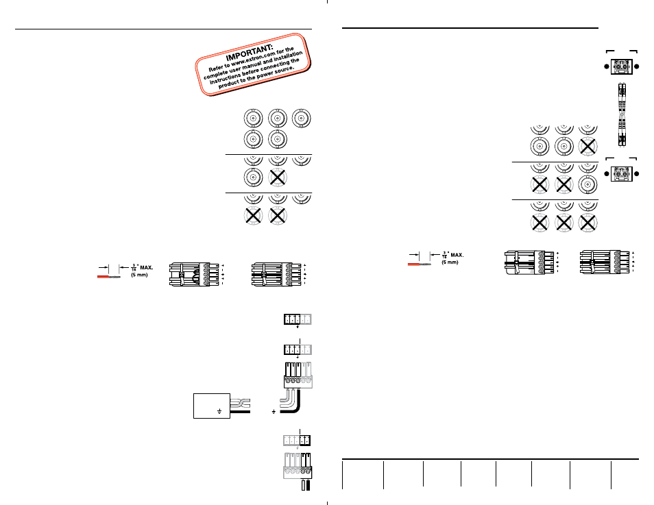
Step 2a — Video input (FOX 500 Tx [analog])
Connect a VGA to UXGA source to the transmitter: either
to the RGB Input 15-pin HD connector or to the RGB Input
BNC connectors. See the drawing at right to wire the BNC
connectors.
Step 2b — Video input (FOX 500 Tx DVI)
Connect a digital visual interface (DVI-D) source to the
transmitter’s DVI-I Input connector.
Step 3 — Local monitor output
If desired, connect a local monitor to the transmitter’s Buffered
Loop-Through 15-pin HD connector or DVI connector, as
applicable.
Step 4 — Audio input
Connect a balanced or unbalanced, stereo or mono audio input to the transmitter: either to the
Audio Inputs 3.5 mm mini jack or to the Audio Inputs 5-pole captive screw connector. See the
drawing below to wire the captive screw connector.
Step 5
— RS-232 over fiber
If you want the FOX 500 to pass serial data and/or control signals, such as for serial
control of a projector, connect the master (controlling) device to the transmitter and
the slave device (projector) to the receiver via three poles of the RS-232 Over Fiber
captive screw connector on both units.
N
For RS-232 responses (from the receiver to the transmitter), you must install
fiber cable Optical 2. See Step 8.
Step 6
— Serial control
For serial control of the transmitter and receiver,
connect a host device to either unit via three poles of
the Remote RS-232/Alarm captive screw connector
or to either unit’s front panel Configuration
connector using an optional TRS RS-232 cable,
part #70-335-01.
Step 7
— Alarms
For remote monitoring of the status of the optical links, connect a locally
constructed or obtained device to the two Alarm poles of the units’ RS-232/Alarm
5-pole captive screw connectors. The two poles are shorted together when no light
is detected.
N
The transmitter’s Alarm port reports the status of the Optical 2 light link.
The receiver’s Alarm port reports the status of the Optical 1 light link.
Step 8
— Fiber cables between units
Connect the Optical 1 (required) and Optical 2 (optional) fiber cables between the
transmitter and receiver.
N
Only Optical 1 is required for video, audio, and serial transmission.
Optical 2 is required only to return serial data from the slave device
connected to the receiver to the master device connected to the transmitter.
Step 9a
— Video outputs
(Fox 500 Rx [analog])
Connect one or two RGBHV, RGBS, or RGsB displays to the receiver, using the
RGB Output 15-pin HD connector and/or the RGB Outputs BNC connectors. See
the drawing below right.
Step 9b
— Video outputs
(Fox 500 DVI Rx)
Connect a DVI display to the receiver’s DVI-I
Output connector.
Step 10
— Audio outputs
Connect balanced or unbalanced stereo or mono
audio devices to the receiver, using the Audio
Outputs 3.5 mm mini jack and/or the Audio
Outputs 5-pole captive screw connector. See the
drawing below.
C
Connect the sleeves to ground (Gnd).
Connecting the sleeve to a negative
(-) terminal will damage the audio output circuits.
Step 11 — Power
Plug standard IEC power cords between the units’ power connectors and 100 VAC to 240 VAC,
50 or 60 Hz power sources.
Step 12
— Optimizing the video
(Fox 500 [analog])
a
. On the receiver, from the default display cycle, press Menu {*5} > Next {*3} to access the
Test Pattern submenu.
b
. Rotate either Adjust knob to select the Alt. Pixels test pattern.
N
Both fiber cables must be installed to access the Total Pixel and Pixel Phase submenu.
c
. On your display, select “auto image” (if available) or adjust the active pixels, total pixels,
and pixel phase for the best picture quality.
d
. Return to the Test Pattern submenu (Menu {*5} > Next {*3}) and rotate either Adjust knob
to deselect the Alt. Pixels test pattern.
e
. From the Test Pattern submenu, press Menu {*3} > Next {*3} to access the Total Pixel and
Pixel Phase submenu.
f
. Rotate the
[
knob to adjust the total pixels and the
{
knob to adjust the pixel phase for the
best picture quality.
g
. Wait for approximately 30 seconds; the receiver returns to the default display cycle.
REMOTE
RS-232
ALARM
Tx Rx
1 2
R
RGBHV
G
B
RGBS
RGsB
R
G
B
R
G
B
V
S
V
H
H
H
S
S
V
OPTICAL
Tx Side
Rx Side
1 2*
*
OPTIONAL FOR
RETURN DATA
LINK
LIN
K
OPTICAL
2* 1
*
OPTIONAL FOR
RETURN DATA
LINK
LINK
Do not tin the wires!
Unbalanced Stereo Output
Balanced Stereo Output
L
R
Ring
Sleeve(s)
Tip
Tip
Ring
Sleeve(s)
Tip
Tip
NO GROUND HERE.
NO GROUND HERE.
RGBHV
H
/HV
V
RGBS
RGsB,
RsGsBs
H/
HV
V
H/HV
V
R
G
B
R
G
B
R
G
B
RS-232
OVER FIBER
Tx Rx
NA
Controlling
Device
Receive (Rx)
Transmit (Tx)
Ground ( )
Receive (Rx)
Transmit (Tx)
Ground ( )
Bidirectional
REMOTE
RS-232
ALARM
Tx Rx
1 2
Unbalanced Stereo Input
Balanced Stereo Input
L
R
L
R
Ring
Sleeve (s)
Tip
Sleeve
Tip
Sleeve
Tip
Tip
Ring
Do not tin the wires!
Setup Guide — FOX 500 and FOX 500 DVI
68-1308-50
Rev. A
04 09
Setup Guide — FOX 500 and FOX 500 DVI