Extron Electronics FOX 3G HD-SDI Setup Guide User Manual
Fox 3g hd-sdi setup guide, Installation, Step 1 — mounting
This guide provides instructions for an experienced installer to set up and operate
Extron
®
FOX 3G HD-SDI Transceiver.
The transceiver can be configured via its rear panel Mode DIP switches to operate in one
of three ways:
•
Bidirectional transceiver
•
Transmitter
•
Receiver
See
on the rear of this guide if you need more information.
NOTE:
In this guide, the term “transceiver” refers to any FOX 3G HD-SDI; the term “bidirectional transceiver” refers to a
FOX 3G HD-SDI specifically configured as a bidirectional transceiver.
Installation
Step 1 — Mounting
Turn off or disconnect all equipment power sources and mount the transceiver as required.
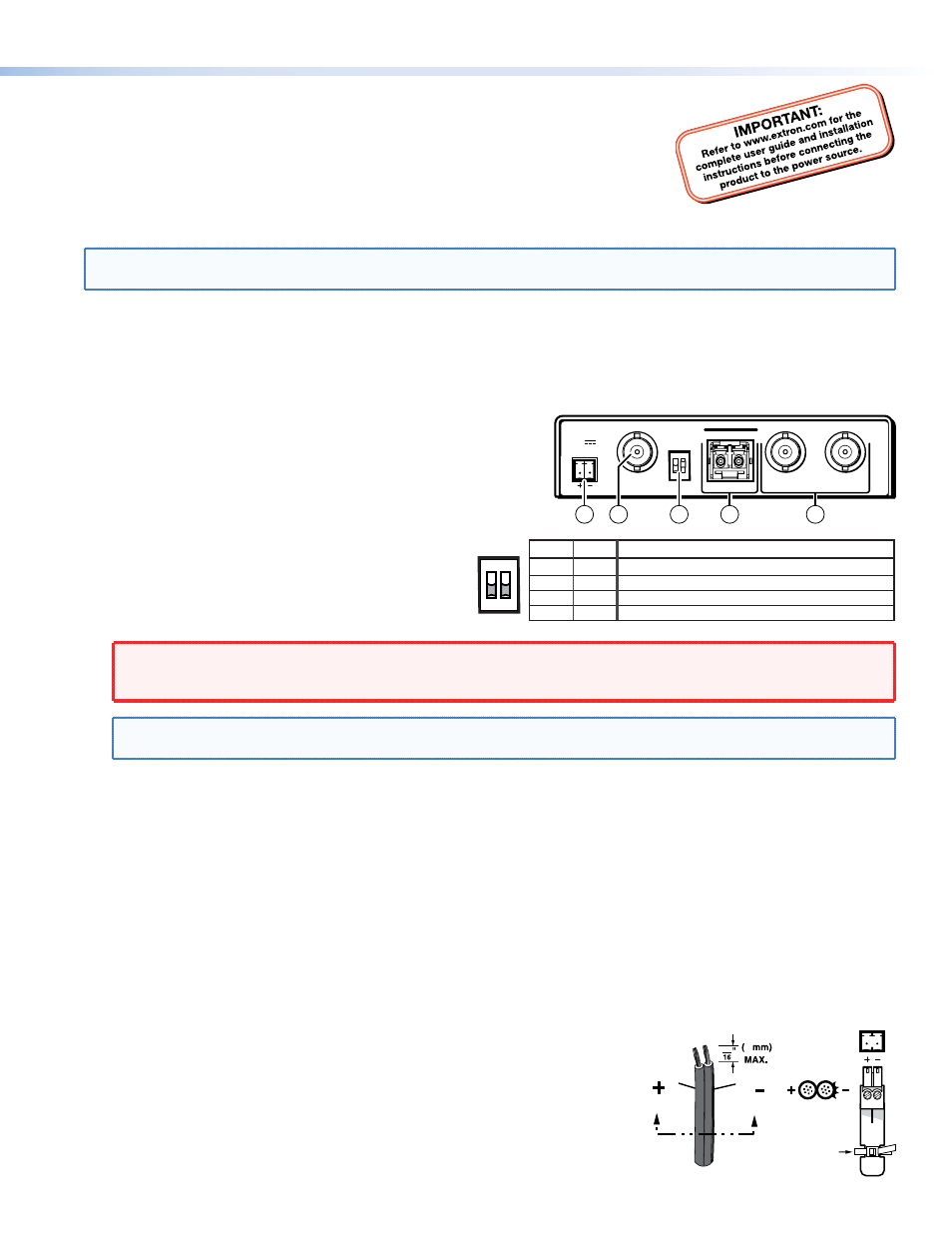
Step 2 — Connections and Initial Settings
a
HD-SDI Input connector — If the FOX 3G HD-SDI is configured as
either a bidirectional transceiver or as a transmitter, connect an
HD-SDI, SDI, or 3G-SDI video input to this BNC connector.
b
Mode switches — Set these DIP switches to the
positions shown at right to select the transceiver
configuration. See
rear of this guide for more information.
c
Fiber optic connectors —
WARNING:
This unit outputs continuous invisible light, which may be harmful to the eyes; use with caution. For
additional safety, plug the attached dust caps into the optical transceivers when the fiber optic cable is
unplugged.
NOTE:
Ensure that you use the proper fiber cable for your transceivers. Typically, singlemode fiber cable has a
yellow jacket and multimode fiber cable has an orange or aqua jacket.
Tx connector — In any configuration, connect a fiber optic cable to the Optical Tx LC connector.
Connect the free end of this fiber optic cable to the Optical Rx connector on another FOX 3G HD-SDI transceiver that is
configured as a bidirectional transceiver or as a receiver.
Rx connector — In either the bidirectional transceiver or receiver configuration, connect a fiber optic cable to the
Optical Rx connector to receive the signal from the transmitting unit. Connect the free end as detailed below:
•
In a 2-transceiver system, connect the free end of this cable to the Optical Tx connector on the transmitting unit,
which is configured as a transmitter.
•
In a daisy-chained system, connect the free end of this cable to the Optical Tx connector on the previous unit in the
daisy chain (configured as either a bidirectional transceiver or a transmitter).
d
Buffered Outputs connectors — In any FOX 3G HD-SDI configuration, connect a digital display to these BNC connectors.
In the bidirectional transceiver configuration, connectors 1 and 2 both output the video that is sent from the other
transceiver.
In the receiver configuration, only connector 2 outputs video and it is the
video sent by the transmitting unit.
In the transmitter configuration, connectors 1 and 2 both output the video
signal that is input on the HD/SDI Input connector,
e
Power connector — Plug the included external 12 VDC power supply into this
2-pole captive screw connector as shown at right. Use the supplied tie-wrap to
strap the power cord to the extended tail of the connector.
12V
0.3A MAX
FOX HDSDI
HD/SDI IN
POWER
BUFFERED OUTPUTS
MODE
OPTICAL
Rx
Tx
1
2
1 2
2
5
1
3
4
SW2 Mode
Down
Down
Up
Up
Down
Up
Down
Up
Bidirectional transceiver (
default position)
Transmitter with local monitor outputs
Receiver with daisy chaining
Spare (functions as receiver with daisy chaining)
SW1
MODE
1 2
Power Supply
Output
Cord
SECTION
A–A
Ridges
Smooth
A
A
Tie Wrap
3
5
1
FOX 3G HD-SDI Setup Guide