Extron Electronics DVS 304 Series Setup Guide User Manual
Dvs 304 series – setup guide, Power and video input connections, Output and control connections
The Extron DVS 304 Series of video and RGB digital scalers incorporate advanced technology
to provide high performance video processing with selectable output rates up to 1920x1200
(DVI models only) and HDTV 1080p, as well as simultaneous DVI (DVI models only) and
analog RGB or component video outputs.
This setup guide allows quick and easy set up and configuration of a DVS scaler using step by step instructions. It covers
performing basic operations using the front panel controls and selected Simple Instruction Set (SIS
™
) commands.
N For full installation, configuration, and operation details, refer to the DVS 304 Series User’s Manual, online at
www.extron.com
.
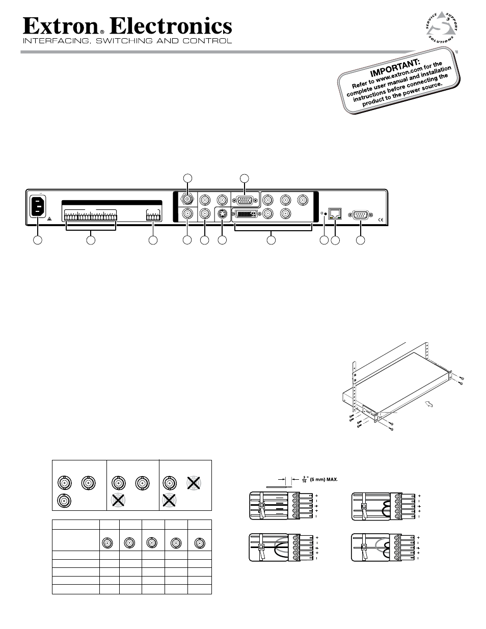
Installation — Rear Panel Features (DVS 304 DVI AD model shown)
INPUTS
OUTPUT
RS-232
LAN
RESET
ACT
LINK
50/60 Hz
100-240V .3A
2
1
3
4
L
R
L
R
L
R
L
R
L
R
AUDIO
VID
1
2
3
4
Y
/VID
R-Y
H/
HV
R
/R-Y
V
G
/Y
B
/B-Y
DVI-I
YC
SDI
B-Y
/C
RGB/R-Y,Y,B-Y/YC/VID
I
N
P
U
T
O
U
T
P
U
T
6
3a
3
7
4
5
9
1
2
11
8
10
DVS 304 DVI AD
Power and video input connections
Output and control connections
a
AC power connector
g
Audio output connectors - (audio models only)
b
Audio input captive screw connectors (inputs 1 to 4) - audio models only
h
RGB/YUV-HD BNC and DVI* output connectors
c
Composite video BNC connector (input 1)
i
Reset button and LED
Ñ
(Optional) SDI BNC connectors (configurable)
j
RJ-45 Ethernet connector
d
Composite video/S-video/component video BNC connectors (input 2)
k
9-pin D RS-232 connector
e
S-video 4-pin mini-DIN connector (input 3)
f
15-pin HD connector (input 4) with EDID emulation*
Installation and cabling
Step 1 — Mount the DVS
Turn off or disconnect all equipment power sources and rack mount the DVS unit, using
suitable mounting brackets or rack shelf (see image at right).
Refer to the DVS 304 Series User’s Manual for details.
Step 2 — Connect inputs
Connect inputs from video and/or audio sources to the applicable connectors marked
“Inputs” (see
b
to
f
above for connector types). See diagrams below for signal format on BNC
connectors and audio input captive screw wiring (balanced or unbalanced, mono or stereo).
N
When connecting a VGA input to a DV 304 DVI model, by default the EDID emulation is set to match the current output rate. To set to a specific rate,
or set to a display's EDID rate, or to upload a custom EDID table refer to the
DVS 304 Series User’s Manual, available at
www.extron.com
.
Component video
(Y, R-Y, B-Y)
S-video
Composite video
B-Y
/
C
Y
/VID
R-Y
B-Y
/C
Y
/VID
R-Y
B-Y
/C
Y
/VID
R-Y
Input 2
Input 4
Pin 1
15-HD pins
Pin 2
Pin 3
Pin 13 Pin 14
Input source
BNC’s
R
V
H
B
G
RGB
RGBcvS
YUV
S-video
Composite video
R
G(S)
B
H
V
R
G
B
cvS
R-Y
Y
B-Y
Y
C
Y
DVS 304 Series – Setup Guide
Rack Mount
Bracket
Unbalanced Stereo Input
Tip
Sleeve
Sleeve
Tip
L
R
Unbalanced Mono Input
Balanced Mono Input
L
R
Tip
Ring
Sleeve
Tip
Ring
L
R
Tip
Sleeve
Tip
Sleeve
Balanced Stereo Input
L
R
Tip
Ring
Sleeve
Tip
Ring
Do not tin the wires!
N
* DVI models only. Non DVI models have a 15-pin HD connector
in place of the DVI connector and do not feature EDID emulation.
68-1039-50
Rev. A
08 09