Connections, Transmitter connections – Extron Electronics DTP HDMI 330 User Guide User Manual
Page 10
DTP HDMI 330 Tx/Rx Transmitter and Receiver • Installation and Operation
4
Connections
Transmitter Connections
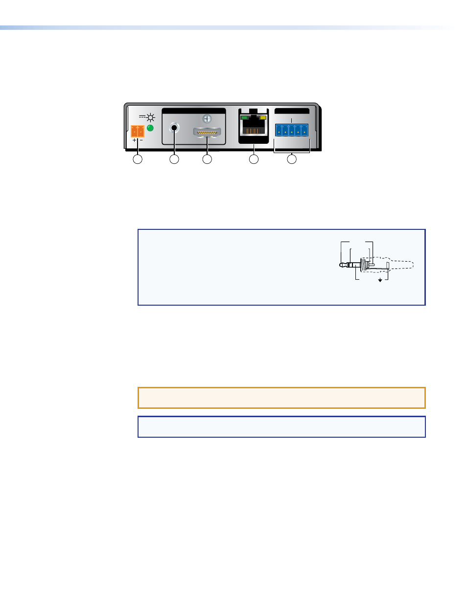
DTP HDMI 330 Tx Rear Panel
POWER
12V
0.7A MAX
AUDIO
SIG LINK
DTP OUT
INPUTS
OVER DTP
RS-232
IR
Tx Rx
Tx Rx
G
3
5
2
4
1
Figure 2.
DTP HDMI 330 Tx Connectors
a
HDMI input connector — Connect an HDMI cable between this port and the HDMI
output port (or DVI port, with an appropriate adapter) of the digital video source.
b
Audio input connector — If desired, plug an analog audio input into the transmitter
via this stereo mini jack connector.
NOTE: The analog audio input on this connector is in
addition to the digital audio that may be embedded
in the HDMI input. See the figure at right to identify
the connector tip, ring, and sleeve when you
are making connections for the transmitter from
existing audio cables. A mono audio connector
consists of the tip and sleeve. A stereo audio
connector consists of the tip, ring, and sleeve.
Sleeve ( )
Ring (-)
Tip (+)
3.5 mm Stereo Plug Connector
(balanced)
c
RS-232 and IR connector — Connect a serial RS‑232 signal, a modulated IR
signal, or both to this 3.5 mm, 5‑pole captive screw connector for bidirectional RS‑232
and IR communication (see
RS-232 and IR connector wiring
to wire the
connector).
d
DTP Output RJ-45 connector — Connect one end of a TP cable to this RJ‑45
female connector on the transmitter. Ensure the opposite end of this cable is connected
to the receiver DTP Input RJ‑45 connector (see
ATTENTION: Do not connect this device to a telecommunications or computer
data network.
NOTE: See
TP cable termination and recommendations
on page 7 to properly
wire the RJ‑45 connectors and for detailed
NOTES.
Signal LED — Indicates the unit is receiving a TMDS clock signal on the HDMI input.
Link LED — Indicates a valid link is established between the units on the DTP input
and output cable.