Setup guide — da av eq series, cont’d, Application diagram, Step 8 — connect audio outputs – Extron Electronics DA AV EQ Series User Manual
Page 2: Step 9 — power on, Yc 1/2, Eq gain, Gain eq gain, Composite video models s-video models
Setup Guide — DA AV EQ Series, cont’d
www.extron.com
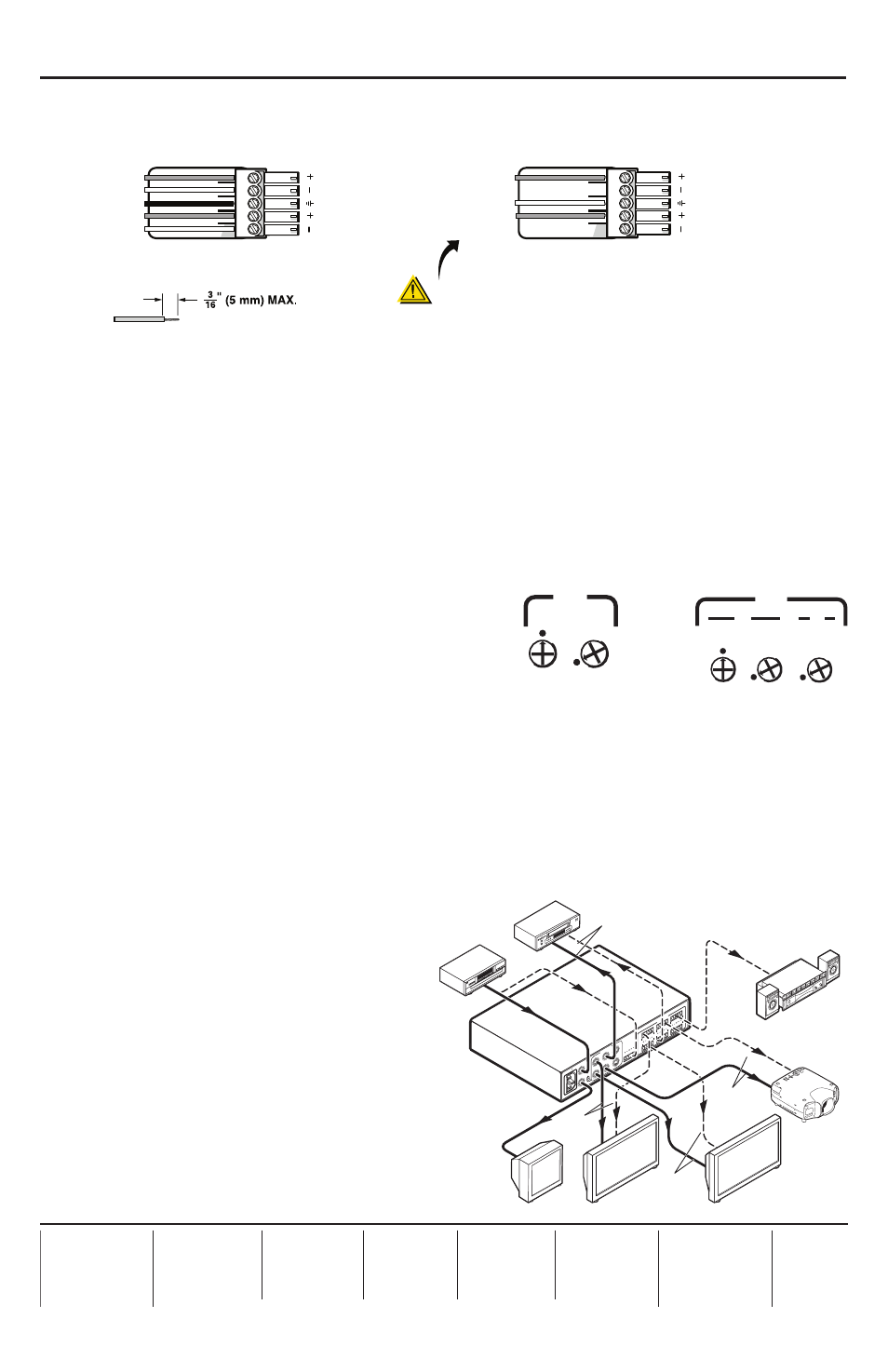
Step 8 — Connect audio outputs
Connect audio output devices to the RCA or captive screw audio Output connectors as shown
below (captive screw) and in Step 7 (RCA).
N
For advanced audio settings, refer to chapter 2, “Installation and Rear
Panel,” of the
DA AV EQ Series User’s Manual.
Step 9 — Power on
Connect power to the DA and to all input and output devices.
Step 10 — Adjust potentiometers for output cable lengths (if
needed)
• If using very short output cables
, ensure that
the potentiometers are in the unity gain position;
that is, with the arrow on each potentiometer
pointing to the dot beside or above it. If the
potentiometers are already in the unity position
(shown in the example for inputs 1 and 2, at
right). Do not change them.
If the potentiometers are not in unity gain
position, rotate them, using a small screwdriver.
• If using long cables
, follow these steps to adjust the potentiometers:
a.
Send the Color Bars test signal to the input, using a video test generator such as the
Extron VTG 300.
b.
Adjust the Gain potentiometers for output pair 1 and 2 until the signal level at the far
end is the same as the input (or the display shows the correct brightness and contrast).
c.
Adjust the EQ potentiometer
for outputs 1 and 2 so that no
overshoot or round front corners
appear at the far end on the scope
(or until you see a sharp picture
with no smearing).
d.
Repeat steps b and c for the rest of
the outputs.
Application Diagram
The figure at right provides an example
of how a DA AV EQ series distribution
amplifier may be connected.
68-977-50
Rev. A
03 10
CAUTION
For unbalanced audio, connect the sleeve(s)
to the ground contact.
DO NOT
connect the
sleeve(s) to the negative (–) contacts.
Tip
Ring
Tip
Ring
L
R
Sleeve(s)
Do not tin the wires!
Tip
NO Ground Here
Sleeve(s)
NO Ground Here
Tip
L
R
Balanced Audio Output
Unbalanced Audio Output
DA
6S
VA
EQ
OU
TP
UT
S
INP
UT
LO
OP
-TH
RU
HIG
H Z
75
Oh
m
5
3
1
6
4
2
50/6
0 H
z
100
-24
0V
0.2
A
INP
UT
OU
TP
UT
S
L
R
L
R
1
2
L
R
L
R
L
R
3
4
L
R
L
R
5
6
Sound System
Projector
DVD
Monitor
(Loop-through)
DA 6SVA EQ
Audio Video
Distribution
Amplifier
HDTV
Plasma
Displays
VCR
6' Cables
800'
Cables
100'
Cables
1000'
Cables
EQ
GAIN
Y
C
1/2
GAIN
EQ
GAIN
1/2
Composite Video
Models
S-video Models