Setup guide — csveq 100 d (cont’d), Step 6 — adjust video gain and equalization, Step 7 — mount the line driver – Extron Electronics CSVEQ 100 D User Manual
Page 2: Figure 6 – application example
Setup Guide — CSVEQ 100 D (cont’d)
Step 5 — Power on the line driver and input/output devices
Wire the power supply (see figure 4) and connect it to the power connector (
h
). When
power is applied to the unit, the front panel LED (
a
) lights.
Connect the power cords of the input and
output devices and turn them on. The
picture should appear and sound should be
audible.
C Always use a power supply
supplied by or specified by
Extron. Use of an unauthorized
power supply voids all regulatory
compliance certification and may cause damage to the supply and the end product.
Unless otherwise stated, the AC/DC adapters are not suitable for use in air handling
spaces or in wall cavities. The installation must always be in accordance with the
applicable provisions of National Electrical Code ANSI/NFPA 70, article 75 and
the Canadian Electrical Code part 1, section 16. The power supply shall not be
permanently fixed to building structure or similar structure.
This product is intended to be supplied by a Listed Power Unit marked “Class 2” or
“LPS”, rated 12 VDC, 1 A minimum.
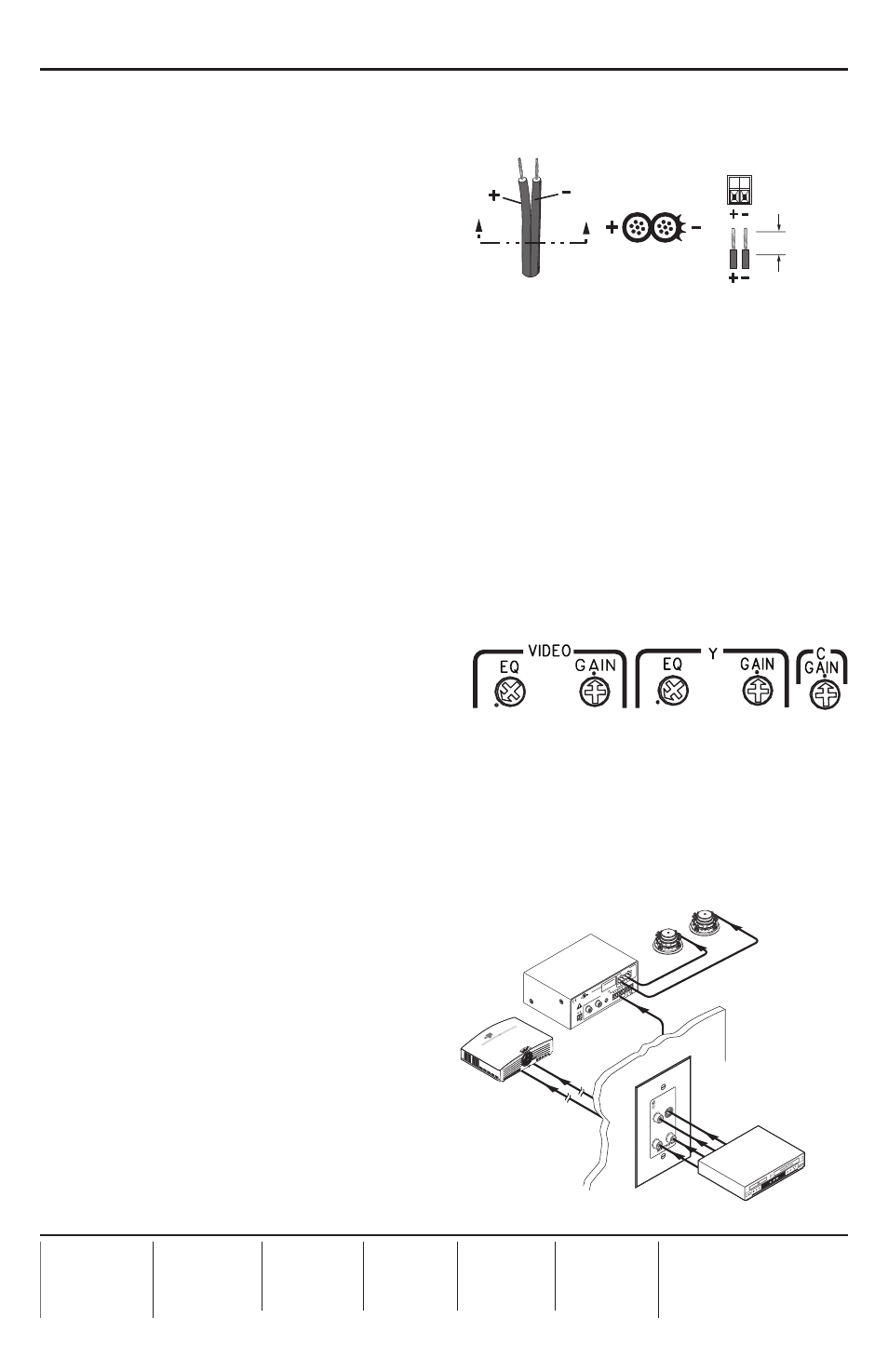
Step 6 — Adjust video gain and equalization
While watching the display, adjust the video gain and equalization (
e
) by using
the rotary gain and equalization (EQ) control potentiometers (see figure 5). Make all
adjustments using a small screwdriver. For
a more precise setting, use an oscilloscope
or a waveform monitor connected to the far
end of the output cable.
If using very short output cables:
• Set all potentiometers to the default setting (the arrow on the control pointing to the dot
beside it, as shown in figure 5).
If using longer output cables:
• Supply the color bars test signal to the input (Recommendation: use an Extron VTG 300
Video Test Generator to generate the test signal).
• Adjust the gain controls for the output until the signal level at the far end is the same
as the input (or the display shows the
correct brightness and contrast).
• Adjust the EQ control for the output
so that no overshoot or round front
corner appears at the far end on the
oscilloscope or you see a sharp picture
with no smearing.
Step 7 — Mount the line driver
Make any cabling adjustments before
mounting the line driver as the cables may
be inaccessible afterwards. Mount the line
driver. For mounting information, see
“Installing the CSVEQ 100 D” in the
CSVEQ 100 D User’s Manual.
68-1598-50
Rev. A
03 10
SECTION A–A
Ridges
Smooth
Power Supply
Output
Cord
A
A
Captive Screw
Connector
3/16”
(5 mm) Max.
Figure 5 – Equalization and gain controls
Figure 4 – Power supply wiring
POWE
R
12V
3A MA
X
OUTPUT
4/8
OHM
S
INPUTS
L
R
L
R
REMOTE
VOL/MUTE
10V
50m
A
L
MP
A 152
R
C
US
LISTED
17T
T
AUDIO/VIDE
O
AP
PA
RA
TU
S
CLAS
S 2 WIRING
DO NOT
GROUND
OR SHOR
T
SPEA
KER OUTPUT
S!
- AUDIO IN
-
L
R
S-VIDEO
IN
VIDEO IN
DVD/VCR
Combo
Extron
MPA 152
Stereo Power
Amplifier
Extron
SI 26X
Two-Way Ceiling
Speakers
Extron
CSVEQ 100 D
Composite Video, S-Video,
and Audio Line Driver
S-video
Composite
Video
1,000 Feet
Projector
Balanced
Audio
Figure 6 – Application example