Front panel controls and indicator, Installation, Operation – Extron Electronics CVDA 6 EQ MX User Manual
Page 2: Description, Installation and rear panel connections, Front panel controls and operations, Specifications, Video input, Video throughput
Front Panel Controls and Indicator
1
CVDA 6 EQ MX Installation and Rear Panel Connections
CVDA 6 EQ MX Operation and Specifications
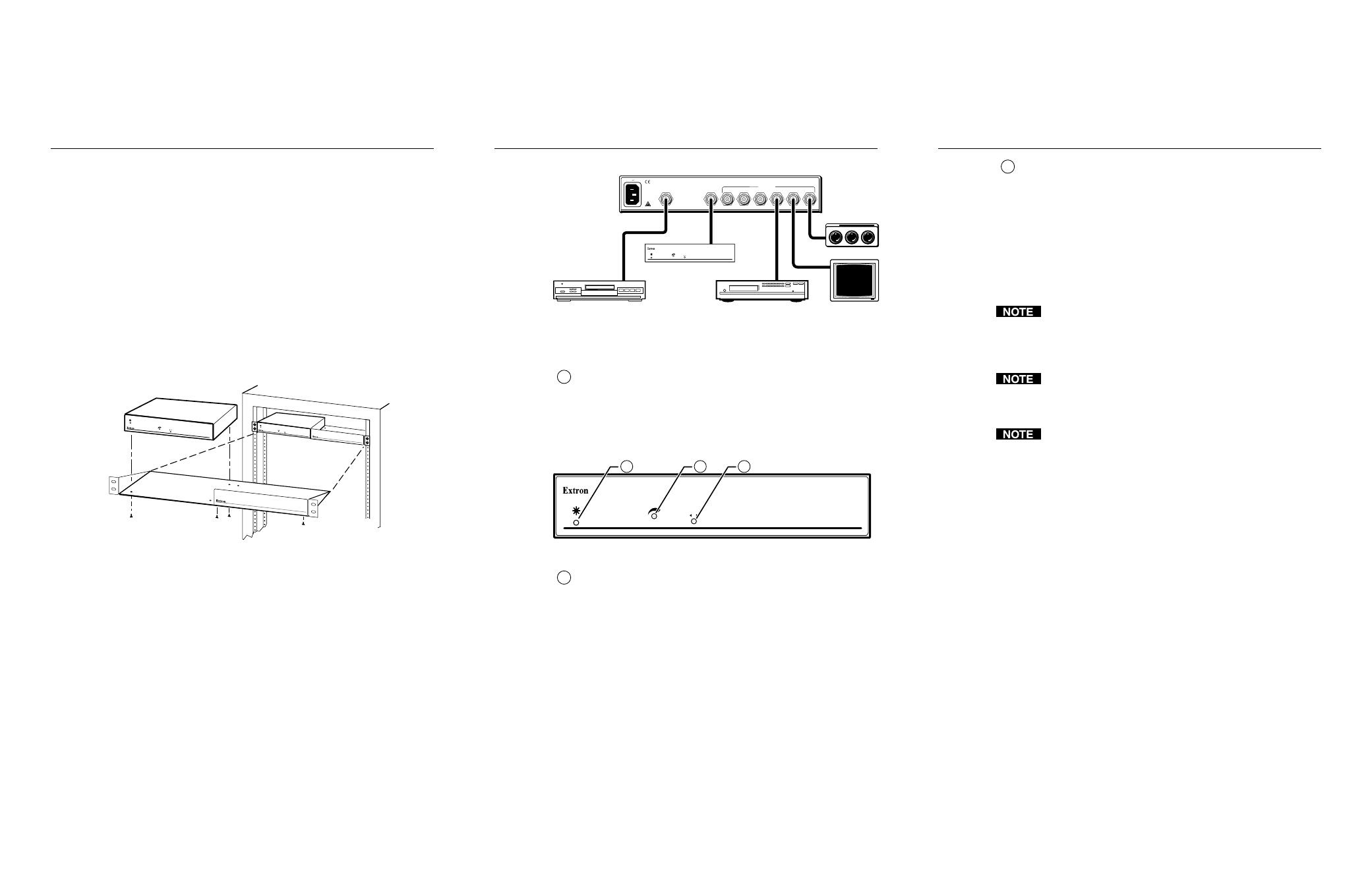
Installation
3
Operation
2
CVDA 6 EQ MX Front Panel Controls and Operations
Description
Extron’s CVDA 6 EQ MX is a 1-input, 6-output composite video
distribution amplifier with level adjustment and equalization
capabilities and a buffered loopout. The adjustments can equalize a
video signal up to 500 feet away on high quality cable such as Extron
SuperFlex SHR Super High resolution coaxial cable. The buffered
loopout is not equalized and is appropriate for connecting a second
CVDA 6 EQ MX or a local monitor.
The CVDA 6 EQ MX is rack mountable and has an internal auto-
switchable power supply that can accept 100VAC to 240VAC at 50 Hz to
60 Hz.
Installation and Rear Panel Connections
1
.
For optional rack mounting, mount the CVDA 6 EQ MX unit on
the left or right side of a 19" 1U Universal Rack Shelf (Extron
P/N 60-190-01) (figure 1).
4-40 X 1/8 Screws
Use 2 Mounting Holes
on Opposite Corners
False Front Panel
Uses 2 Front Holes Only
CVDA 6 EQ MX
COMPOSITE VIDEO
DISTRIBUTION/EQ
UALIZATION AMP
LIFIER
CVDA 6 EQ MX
COMPOSITE
VIDEO DISTRIB
UTION/EQUALIZA
TION AMPLIFIER
LEVEL
EQUALIZE
MAX
MIN
LEVEL
EQUALIZE
MAX
MIN
Figure 1 — Rack mounting the CVDA 6 EQ MX
a
.
If feet were previously installed on the bottom of the case,
remove them.
b
.
Mount the CVDA 6 EQ MX on the rack shelf, using two
4-40 x 1/8 screws in opposite (diagonal) corners to secure the
case to the shelf.
2
.
Connect the composite video input to the input BNC connector on
the rear of the CVDA 6 EQ MX (figure 2).
3
.
Connect the desired devices to the composite video output BNCs
on the rear of the CVDA 6 EQ MX.
4
.
Connect power to the CVDA 6 EQ MX.
OUTPUTS
INPUT
BUFFERED
LOOP-OUT
100-240V 50-60Hz
0.35A
1
2
3
4
5
6
CVDA 6 EQ MX
Projector
Monitor
DVD player
CVDA 6 EQ MX
Up to 6
outputs
LEVEL
EQUALIZE
MAX
MIN
COMPOSITE VIDEO DISTRIBUTION/EQUALIZATION AMPLIFIER
CVDA 6 EQ MX
VCR
Figure 2 — Typical CVDA 6 EQ MX application
Front Panel Controls and Operations
1
Power LED
— This LED (figure 3) lights to indicate that the
CVDA 6 EQ MX is receiving power.
Operation
— After the CVDA 6 EQ MX and its connected devices
are powered up, the system is fully operational. If any problems
are encountered, verify that the cables are routed and connected
properly.
LEVEL
EQUALIZE
MAX
MIN
COMPOSITE VIDEO DISTRIBUTION/EQUALIZATION AMPLIFIER
CVDA 6 EQ MX
1
2
3
Figure 3 — CVDA 6 EQ MX front panel
2
Level adjustment
— This control is similar to a TV’s brightness
control. The level adjustment compensates for signal amplitude
losses caused by cable resistance. The control adjusts the
composite video output signal gain, through one full turn, from -
6dB through +6dB.
Operation
— With a waveform monitor connected to the far end
of one of the output cables, adjust the level so that the level is
100 IRE.
If no waveform monitor is available, adjust the level to boost the
level to achieve the best possible image.
3
Equalize adjustment
— This control is similar to a TV’s
sharpness control. The equalization adjustment compensates for
losses due to capacitance over long cable runs. The control
adjusts the peaking, through multiple turns, between 0 and +4dB.
Operation
— With a waveform monitor connected to the far end
of one of the output cables, adjust the equalization so that the
color burst ranges between -20 IRE and +20 IRE.
If no waveform monitor is available, adjust the equalization to
restore the frequency response and achieve the best possible
image.
The equalize adjustment is a 15-turn potentiometer with a soft
mechanical stop at the high or low end. If you have reached the
high or low end of the adjustment, the potentiometer makes a
clicking sound as you turn it, and no change is apparent on the
display.
The level and equalization adjustments affect all six output
channels simultaneously and equally. For maximum effectiveness
of the level and equalization controls, all display devices should be
connected with cables of equal length.
The level and equalization adjustments have no affect on the
buffered loopout, which should not be run the long distances as
the amplified outputs.
Specifications
Video input
Number/signal type ................... 1 composite video
Connectors .................................... 1 BNC female
Nominal level ............................... Analog ....... 1.0V p-p
Minimum/maximum levels ...... Analog ......... 0.4V p-p to 2.0V p-p with no offset
Impedance .................................... 75 ohms
Maximum DC offset ................... 1.0V
Video throughput
Equalization ................................. 0 to +4dB (over a 0.5 MHz to 8 MHz range)
Level adjust .................................. -6dB to +6dB
Bandwidth .................................... 30 MHz (<±0.5dB), fully loaded
Differential phase error .............. 1º, 3.58 MHz
Differential gain error ................ 0.05%, 3.58 MHz
Crosstalk ....................................... -50dB @ 3.58 MHz