Application, Features, Installation – Extron Electronics ADA 2-4-6 Series User Manual
Page 2: Operation, Ada 2 models, internal jumpers
Analog Distribution Amplifiers • Features
Application
1
2
Analog Distribution Amplifiers • Installation and Operation
1
Extron’s Analog Distribution Amplifiers (ADAs) are designed for use
when one RGB signal must be sent to multiple outputs while
maintaining signal quality. Several models are shown in this user guide,
each with its own features and number of outputs. The model best
suited for any particular application depends upon the number of
outputs needed and the resolution and scan frequency of the signal to be
distributed. As a rule of thumb, the higher the resolution and scan
frequency, the higher the bandwidth required, in order to maintain
optimum picture quality.
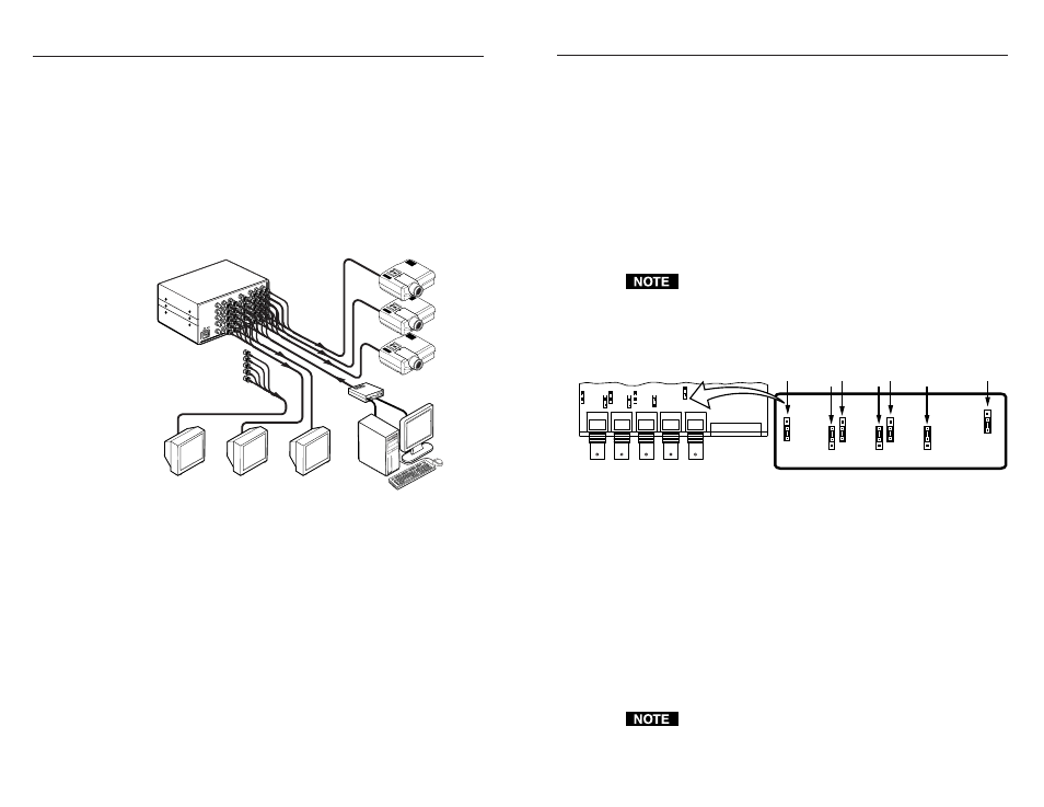
The illustration below is an example showing an ADA 6 distributing the
video from one source to six destinations. Two ADAs could be
connected together for a total of 11 outputs.
Hi-Res Workstation
Display Monitors
Projectors
Interface
Extron
ADA 6 300 MX HV
Features
• Accepts RGB with sync on green, separate composite sync, separate
H&V sync or NTSC/PAL video (certain models).
• High RGB bandwidth allows for signal distribution with no loss of
picture quality.
• Loop output for ganging units together to provide additional outputs
(certain models).
• All outputs are separately buffered and isolated.
• TTL or analog sync output selector switch allows you to choose
between output sync levels (sync gain).
Installation
To install an Extron ADA, do the following:
1
.
Remove power to the ADA and all computers and other devices
that will be connected during the installation procedure.
2
.
For rack mounting, first mount the ADA to a rack front panel, or
universal rack shelf, and then mount the assembly in the rack.
3
.
Connect the input BNC connectors to the signal source, such as
computer video through a video interface. Depending on the
model of your ADA, there are either four connectors (marked R, G,
B, and S) or five connectors (marked R, G, B, HV, and V).
4
.
Connect each output to its destination (such as a monitor or
projector).
5
.
Apply power to the ADA(s) and other devices, PC computer, local
monitor, and other display device(s).
If looping ADAs, choose which unit will be #1 and connect one of
its outputs to the input on ADA #2.
ADA 2 models, internal jumpers
Internal jumper settings for the ADA 2 300 HV model are shown below.
.7V 1V
.7V 1V
DC A
C
4.O
V
1.O
V
.7V 1V
DC A
C
DC A
C
R G B H/HV V
RED
GAIN
OFFSET
GREEN
GAIN
OFFSET
BLUE
GAIN
SYNC
GAIN
OFFSET
JUMP2
JUMP1 JUMP4
JUMP3 JUMP6
JUMP5
JUMP8
Operation
There is little involved in the operation of an ADA. All models, except
for the ADA 2, have toggle switches on the rear panel. A small arrow
identifies the default position for each switch.
1
.
The Video Gain switch is normally set at 0.7V (down). For
installations with long output cable runs, the 1V (up) position will
give a better picture.
2
.
The Sync Gain switch is normally set at 4V (up), for TTL sync. For
the few applications where analog sync is used, this switch should
be in the 1V (down) position.
3
.
AC/DC coupling switches are normally set to the AC position.
Some applications may require that these switches be set to the DC
position.
If the Sync Gain switch is set for 1 V (down) when it should be at
4V, the result will be an unstable or blanking picture.