John Wood Indirect Water Heaters User Manual
Page 3
– 3 –
Location
1. Do not locate the heater where water lines could be
subjected to freezing temperatures.
2. It is desirable to have a floor drain nearby to permit easy
draining if necessary.
3. The drain valve and all access panels must be accessi-
ble for maintenance and service.
4. Install the water heater so that if there is a leak, the
resulting flow of water will not cause damage to the area
adjoining the water heater. Under no condition is the
manufacturer liable for any water damage in connection
with this water heater.
Plumbing
1. Ensure the heater is level before starting the installa-
tion.
2. Install a shut-off valve in the cold water line. This is for
emergency shut-off. It must be kept open during the
heater's operation.
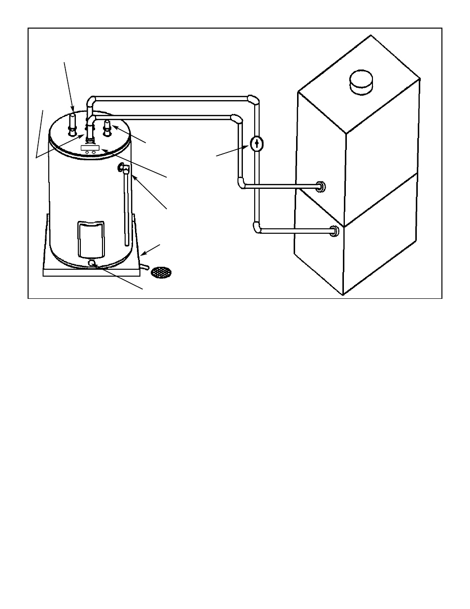
3. A certified relief valve must be installed as shown in
Figure 1.
DO NOT OPERATE THE HEATER WITHOUT A RELIEF
VALVE - SEE NOTE ON RELIEF VALVE.
4. When using copper piping, solder a piece of tubing to a
threaded adaptor before screwing the adaptor to the
tank. Do not apply heat directly to inlet or outlet con-
nections.
5. Install a drip tube from the relief valve terminating at
sink or drain.
DO NOT CAP OR THREAD THE END OF A DRIP TUBE -
IT MUST BE UNOBSTRUCTED AND FULL SIZE.
6. The two threaded pipe nipples which are supplied with
the heater should be attached to the "Boiler In" and
"Boiler Out" connections. Connect the "Boiler In" fitting
of the heater to the "supply" fitting of the Boiler and
"Boiler Out" fitting of the heater to "return" fitting of the
Boiler. A suitable circulator pump should be placed
between "Boiler Out" at the heater and "Return" at the
water heater. See Figure 1.
Wiring
1. Remove Access cover on top of the heater.
2. Connect wiring to circulator pump as shown in Figure 2.
A No. 14 AWG Type TEW 105°C wire was installed in
this heater. If wire has to be replaced in the field, use
only type TEW 105°C wire.
3. A ground wire must be run from the ground screw at the
heater junction box to the ground connection at the
service panel.
4. The maximum inductive rating of this circuit is 7.2 F.L.A
120 VAC. Do not exceed this rating.
5. Ensure that wiring conforms to local codes.
Filling
To fill the heater:
1. Open a hot water faucet.
2. Open the cold water supply valve.
3. When water runs out of the hot faucet the tank is filled.
4. Check the system for leaks.
PLEASE REFER TO BOILER MANUFACTURER
INSTRUCTIONS FOR PLUMBING CONNECTION
GUIDELINES.
HOT WATER OUTLET
CIRCULATION PUMP
BOILER OUT
RETURN
BOILER IN
COLD WATER INLET
DRAIN VALVE
DRAIN PAN
SUPPLY
T & P RELIEF VALVE
BOILER
JUNCTION BOX
E L E C T R I C A L
CONNECTION
Figure 1 Plumbing
ANODE