Xylem TB500 ONLINE TURBIDITY ANALYZERS User Manual
Page 7
TB500 (2/07)
Rev. 1.0
3
1.2 Unpacking and Inspection of the Instrument and Accessories
The table below indicates the items in the turbidimeter shipment.
Item Quantity
TB500 Turbidimeter c/w Field Terminal Box & Flow Through Assembly
1
Instruction Manual
1
Desiccant Pack
1
Cuvette (Single Pack)
1
Tubing Kit: 1-shutoff clamp
1-backpressure valve
2-connecting tubing with fittings for flow through assembly
1-drain vent screw (used in pressurized systems)
1
Remove the instrument from the packing carton. Carefully inspect all items to ensure that
no visible damage has occurred during shipment. If the items received do not match the
order, please immediately contact the local distributor or the Global Water’s Customer
Service department.
Note: The spare cuvette, TB502-CUV, is not included for models TB504-WL & TB504-IR.
In these models a special ultrasonic cuvette, TB500-UCUV, is provided. This cuvette
must be installed prior to operating the instrument.
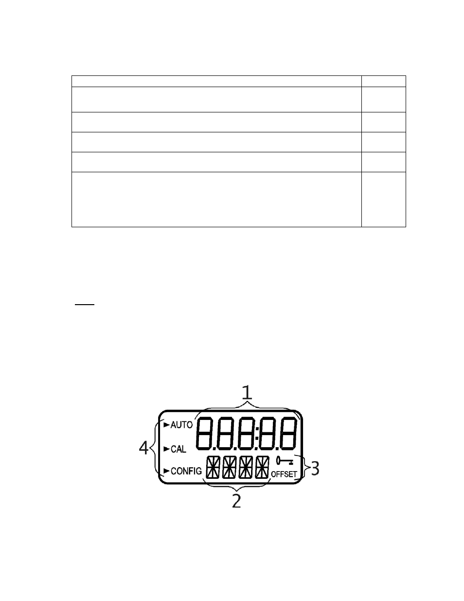
1.3 The Display
Figure 1 illustrates all the items that can appear on the display. The upper row of the
display (1) is used for reporting the turbidity levels and to provide user guidance in the
customer setting routine. The lower row of the display (2) is used to communicate error
messages and provide user guidance. The display has two icons (3) that are used to
indicate the use of access code and offset mode. In addition, mode arrows (4) are used to
indicate the current instrument operating mode; AUTO (normal operation), CAL
(calibration) and CONFIG (configuration).
Figure 1 – Display used in the instrument.
All items used on the display are shown in this figure