Step 4 - electrical installation, Warning – Xylem MM 601H Series FS4-3 General Purpose Liquid Flow Switch User Manual
Page 6
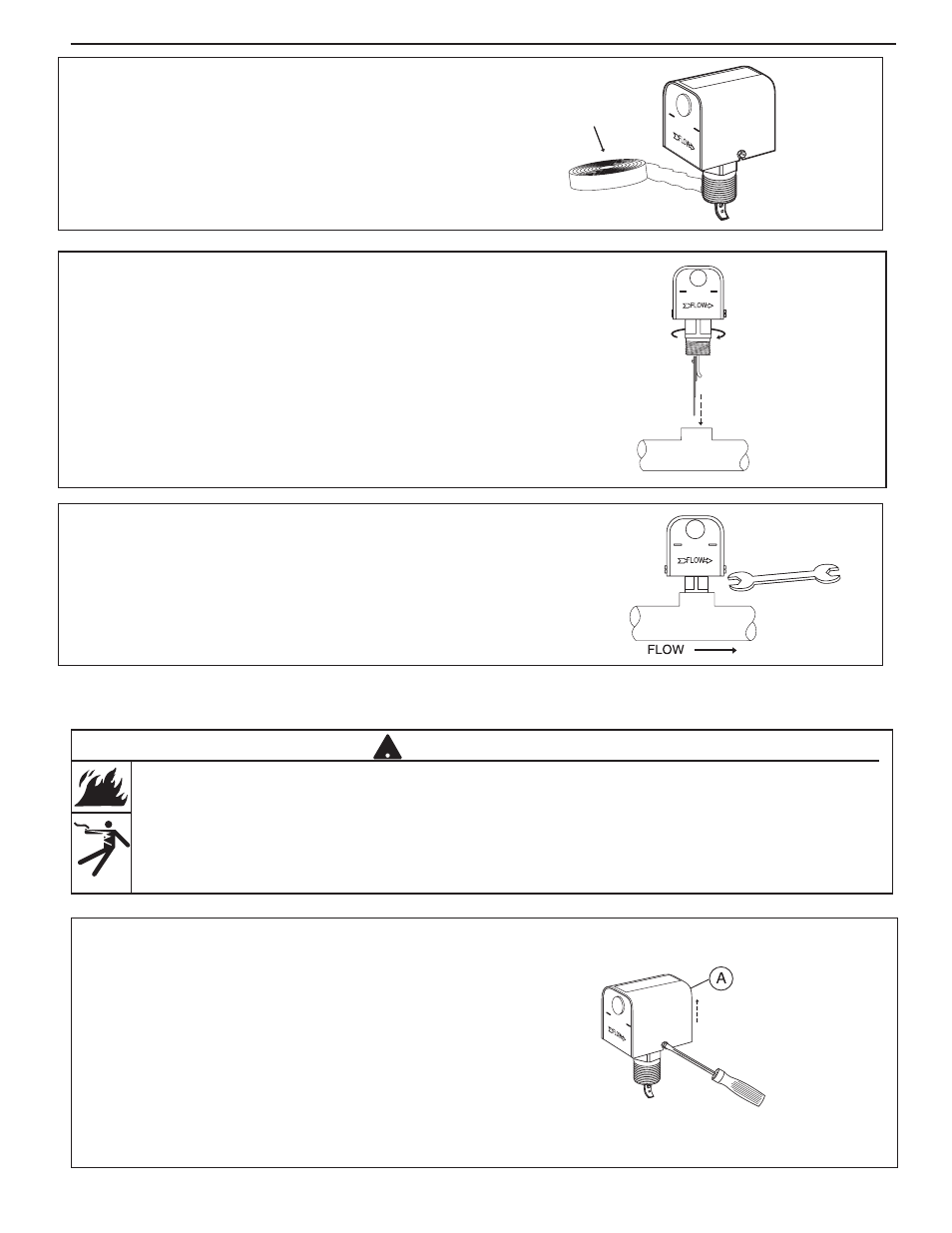
a. Cover Removal and Installation Procedure
• Using a flathead screwdriver, loosen but do not
remove the two cover screws and remove the
cover (A).
• Place the cover on the flow switch sliding the slots
behind the two loose cover screws. Push the cover
down into the flow switch and using a flat blade
screwdriver, tighten the cover screws to a torque
of 10 lb•in (1.13 N•m).
STEP 4 - Electrical Installation
• To prevent electrical shock, turn off the electrical power before making electrical connections.
• To prevent an electrical fire or equipment damage, electrical wiring insulation must have a rating of
167˚F (75˚C) if the liquid’s temperature exceeds 180˚F (82˚C).
• To prevent electrocution, when the electrical power is connected to the flow switch, do not touch the
terminals.
• Make sure flow switch electrical cover is secured before turning on electric power.
Failure to follow this warning could cause property damage, personal injury or death.
6
!
WARNING
c. Insert the flow switch into the pipe tee. Turn
the flow switch two (2) or three (3) revolutions
clockwise until tight. Do not put excessive
force on cover when turning.
d. Place a 1 3/8" open end wrench on flow switch
body to tighten to final position. Final position
is with arrow on housing aligned in the same
direction as liquid flow.
b. Apply pipe sealing compound or PTFE tape to the
flow switch pipe threads.
NOTE: Do not apply sealant to first threads as this
switch is grounded (earthed) via the pipe mounting.
PTFE