Step 4 - electrical wiring, Warning, Circuit board layout – Xylem MM 415C Replacement Head Mechanism 150E HD User Manual
Page 10: Probe connections, 60 second adjustable burner off delay, Burner terminals pump terminals, Probe led's
10
STEP 4 - Electrical Wiring
• To prevent electrical shock, turn off the electrical power before making electrical connections.
• This low water cut-off must be installed in series with all other limit and operating controls installed on the
boiler. After installation, check for proper operation of all of the limit and operating controls, before leaving
the site.
• Boiler manufacturer schematics should always be followed. In the event that the boiler manufacturer’s
schematic does not exist, or is not available from the boiler manufacturer, refer to the schematics provided
in this document.
Failure to follow this warning could cause electrical shock, an explosion and/or a fire, which could result in
property damage, personal injury or death.
!
WARNING
L
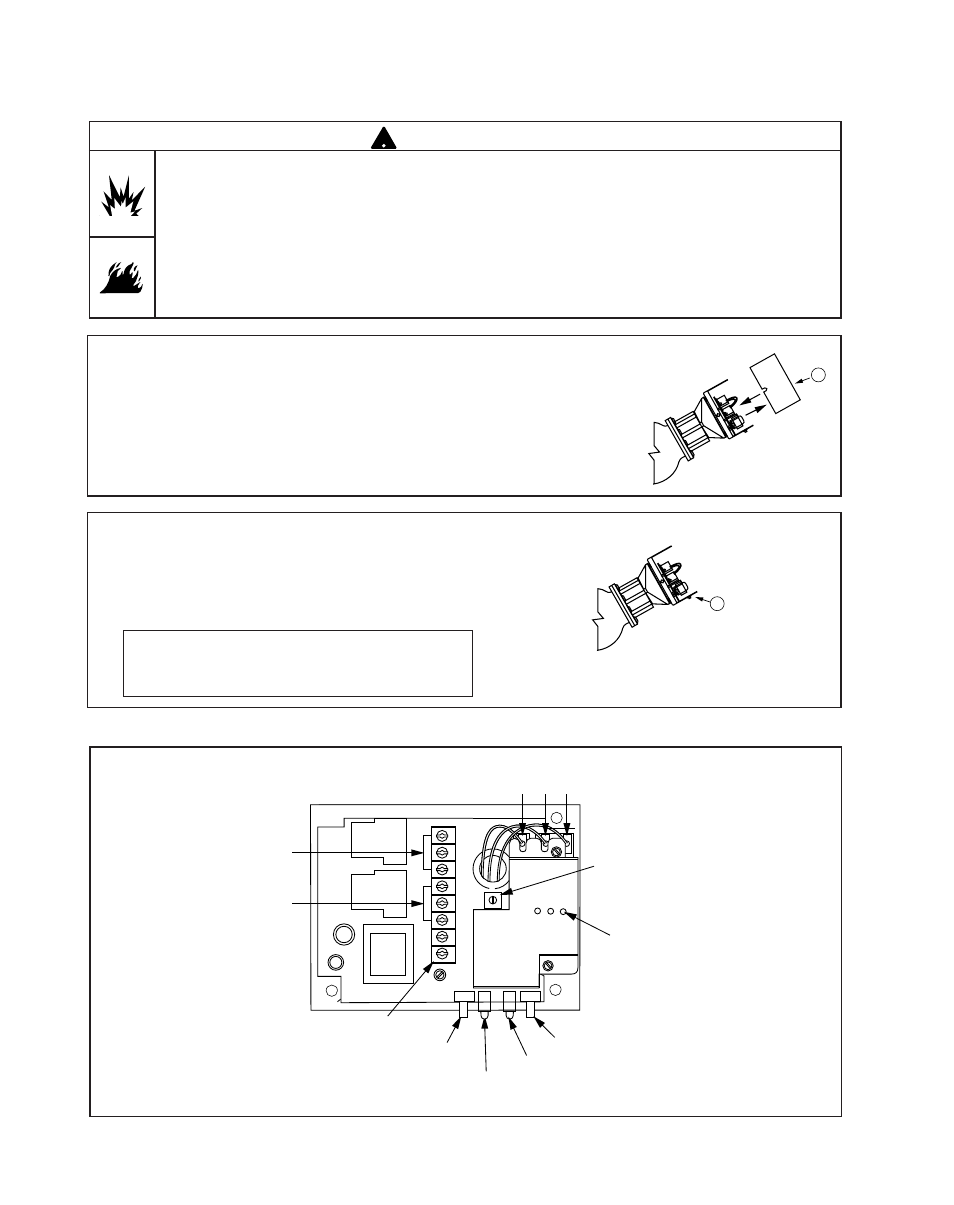
Cover Removal and Installation Procedure
a. To remove cover, use a flathead screwdriver to
loosen screws and remove the cover (K).
b. To reconnect cover, slide over brackets and tighten
screws using a flathead screwdriver.
c. Following the appropriate wiring diagram (refer to
page 11) based on your application requirements,
and using BX armored cable or Thinwall electrical
metal tubing connector fittings, make electrical
connections to the junction box (L).
IMPORTANT: There must be a minimum space
of 2” (13mm) between connector fittings and
electrical live metal parts.
Circuit Board Layout
BCOM
BNC
BNO
PCOM
PNC
PNO
N
H
BCOM
BNC
BNO
PCOM
PNC
PNO
N
H
60
30
Secs
.
0
60
30
Secs
.
0
BCOM
BNC
BNO
PCOM
PNC
PNO
N
H
0
60
30
Secs
.
0
Probe Connections
Bottom
Red
Middle
Yellow
Top
Blue
0-60 Second Adjustable
Burner Off Delay
110 Volt Input
from Boiler
Circuit
Manual Reset
(If applicable)
Low Water
LED
Red
Power
LED
Green
Test
Switch
Burner
Terminals
Pump
Terminals
BCOM
BNC
BNO
PCOM
PNC
PNO
N
H
Probe LED's
K