Wiring diagram legends, Important – Xylem MM 307H Series 101-A Electric Water Feeder User Manual
Page 4
BURNER
CIRCUIT
JUMPER
120 VAC
SUPPLY
1
2
3
4
NEUTRAL
HOT
101A
WATER FEEDER
A
B
67 LOW WATER
CUT-OFF
4
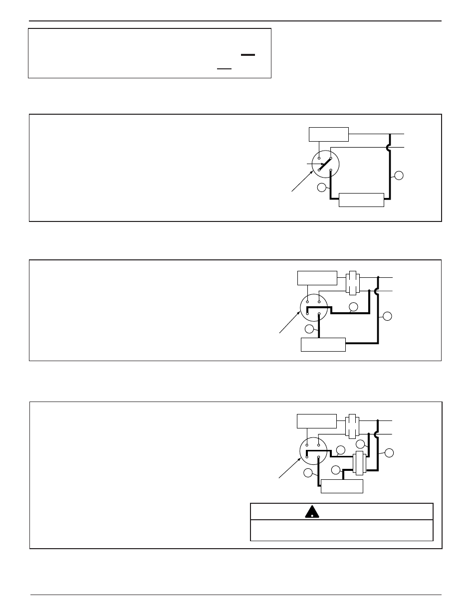
For McDonnell & Miller Model 101A-120 Water Feeder and Series 67 Low Water Cut-Off
with 120 volt burner circuit
h.
Connect wire (A) from water feeder to burner circuit
Neutral wire.
i.
Install jumper between terminals 2 and 3 of the low
water cut-off.
j.
Install wire (B) from water feeder to terminal 4 of the
low water cut-off.
120 VAC
SUPPLY
1
2
3
4
NEUTRAL
HOT
24V
A
B
C
101A
WATER FEEDER
67 LOW WATER
CUT-OFF
BURNER
CIRCUIT
For McDonnell & Miller Model 101A-120 Feeder and Series 67 Low Water Cut-Off
with 24 volt burner circuit
h.
Install wire (A) from water feeder to 120 volt Neutral wire.
i.
Install wire (B) from water feeder to terminal 4 of the low
water cut-off.
j.
Install wire (C) from terminal 3 of the low water cut-off
to 120 volt Hot wire.
120 VAC
SUPPLY
1
2
3
4
NEUTRAL
HOT
101A
WATER FEEDER
24V TRANSFORMER
(101-24 V-48)
24V
A
B
C
D
E
67 LOW WATER
CUT-OFF
BURNER
CIRCUIT
For Model 101A-24 Water Feeder and Series 67 Low Water Cut-Off
with 24 volt burner circuit
h.
Install wire (A) from burner circuit Neutral wire
to the transformer input Neutral terminal.
i.
Install wire (B) from burner circuit Hot wire to the
transformer input Hot terminal.
j.
Install wire (C) from transformer output Neutral
terminal to the water feeder.
k.
Install wire (D) from the water feeder to terminal 4
on the low water cut-off.
l.
Install wire (E) from terminal 3 on the low water
cut-off to the transformer output Hot terminal.
Wiring Diagram Legends
1.
Bold lines indicate action to be taken in Step shown.
2.
Regular black lines indicate existing wiring.
To prevent damage to the water feeder, a McDonnell
& Miller transformer Model 101-24V-48 must be used.
!
IMPORTANT