Installation, Important – Xylem MM 307H Series 101-A Electric Water Feeder User Manual
Page 2
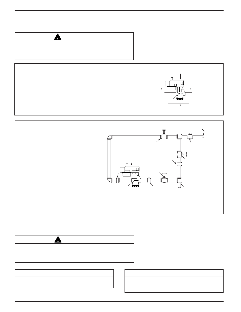
FLOW
ARROW
6" (152mm)
6" (152mm)
6"
(152mm)
6"
(152mm)
2
Determine where to install the water feeder
based on the following requirements:
a.
It must be installed within eyesight of the boiler.
b.
A minimum 6” (152mm) clearance should be
allowed on all sides for servicing.
c.
It must be installed in a horizontal pipe in the
upright position.
d.
It should be installed on the cold water line.
BYPASS VALVE
OUTLET VALVE
CHECK VALVE OR BACK
FLOW PREVENTER
(MAY BE REQUIRED BY
LOCAL CODE OR
ORDINANCES)
INLET VALVE
FLOW ARROW
CONNECT TO
RETURN HEADER
ON BOILER
NOTE:
DO NOT CONNECT
DIRECTLY TO BOILER SHELL
WATER FEEDER
CITY WATER SUPPLY
UNION
UNION
UNION
Installation Diagram and Requirements
a.
Piping must be 1/2” (15mm) NPT
minimum.
b.
Full port/full flow valves rated for the
pressure/temperature of the system
and piping they are to be installed on.
c.
Arrow on feeder casting must point in
direction of flow into the boiler.
d.
Install isolation valves and unions on
the inlet and outlet piping of the feeder
for easier trouble-shooting and repair/
replacement.
e.
Install manual fill valve and bypass line
to allow for removal of the valve while
the boiler is in service.
STEP 1 - Determine Where to Install the Water Feeder
STEP 2 - Electrical Installation
INSTALLATION
Boiler manufacturer schematics should always be followed. In the
event that the boiler manufacturer’s schematic does not exist, or is
not available from the boiler manufacturer, refer to the schematics
provided in this document.
!
IMPORTANT
Boiler manufacturer schematics should always be followed. In the
event that the boiler manufacturer’s schematic does not exist, or is
not available from the boiler manufacturer, refer to the schematics
provided in this document.
!
IMPORTANT
Before connecting water feeder, operate boiler and
check all safety devices.
NOTE
Unless otherwise noted, water feeder voltage
should be the same as the LWCO and burner
circuit voltage.
NOTE